
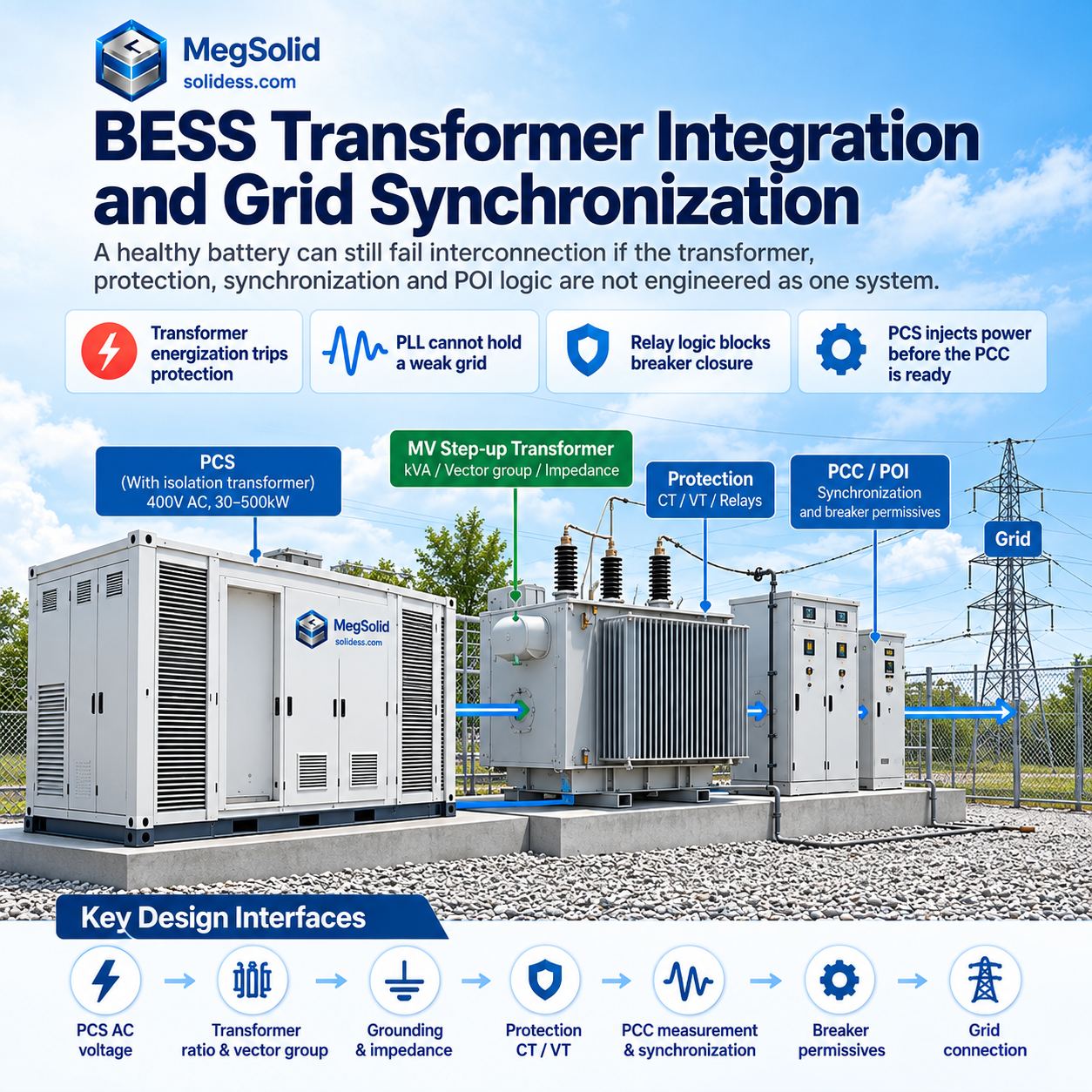
A BESS does not fail interconnection because the battery has no energy. It fails because the transformer, protection, synchronization and POI logic were never engineered as one system.
The single-line diagram matters because it defines how the transformer, protection, synchronization and POI logic work together.
Projects can have a healthy DC battery and still fail SAT if transformer energization trips protection, the PLL cannot hold a weak grid, relay logic blocks breaker closure, or the PCS injects power before the PCC is ready.
MegSolid se MEGA 30–500kW PCS provides bidirectional conversion, configurable active/reactive power, 400V AC operation and an isolation-transformer architecture.
That PCS isolation transformer is not automatically the same thing as the project MV step-up transformer.
These transformers perform different engineering functions.
Large C&I projects may still require a separate transformer between the PCS AC bus and the medium-voltage point of interconnection.
Do not treat one as a substitute for the other unless the approved system architecture explicitly combines both functions.
Freeze the Transformer and Synchronization Chain Before SLD Release
PCS voltage → transformer ratio → vector group → grounding → impedance → protection → PCC measurement → synchronization logic → breaker permissives
If one of those interfaces is missing, the design error often appears during commissioning.
10-Step BESS Transformer Integration & Grid Synchronization Process
| Fase | Engineering Check |
|---|---|
| 1 | Confirm PCS AC voltage and required grid interconnection voltage |
| 2 | Select transformer ratio, vector group, kVA, impedance and grounding |
| 3 | Confirm CT/VT locations and protection boundaries |
| 4 | Energize auxiliary power, BMS, PCS controls and protection relays |
| 5 | Energize the transformer using the approved energization sequence |
| 6 | Verify PCC voltage, frequency and phase sequence |
| 7 | Acquire grid reference / PLL lock where GFL control is used |
| 8 | Verify voltage, frequency, phase-angle and breaker permissives |
| 9 | Close the approved AC/MV breaker and ramp active/reactive power |
| 10 | Verify PCC power quality, relay status and stable operation |
If the SLD cannot explain these ten stages, the synchronization process is not fully defined.
Specify the Step-Up Transformer From Actual BESS Converter Duty
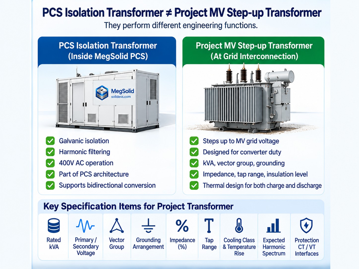
The label “BESS transformer” does not define whether a transformer is suitable for converter duty.
Suitability depends on whether the electrical and thermal design matches the actual converter duty.
Check Transformer Duty in Both Power-Flow Directions
Do not reject a transformer simply because it was previously described as “PV” or “distribution.”
Do not approve it only because the kVA rating looks large enough.
Transformer duty matters more than the charge/discharge label alone.
BESS operation can include:
- charge from the grid
- discharge to the grid
- change active-power direction repeatedly
- supply or absorb reactive power
- operate near rated output for long periods
- cycle between different thermal states
The transformer must be checked for the actual loading profile in both directions.
The SLD and transformer specification should define:
- primary and secondary voltage
- rated kVA
- vector group
- grounding arrangement
- insulation level
- impedance
- tap range
- cooling class
- temperature rise
- expected harmonic spectrum
- protection CT/VT interfaces
MegSolid se 500kW transformer and grid-connection boundaries show why transformer capacity cannot be checked from BESS kW alone.
A 500kW PCS can also move reactive power.
The transformer and switchgear must be evaluated in kVA, not only kW.
Evaluate Harmonics Before Specifying K-Factor
Do not put “K-13 transformer required” into a BESS specification because someone copied it from a data-center project.
A copied K-factor requirement is not a substitute for harmonic analysis.
Power converters produce non-sinusoidal current components, but the correct response is to evaluate the actual spectrum and the PCC limits.
IEEE 519 addresses harmonic performance at the point of common coupling.
IEEE C57.110 provides a framework for evaluating transformer capability under non-sinusoidal currents.
K-factor ratings may be appropriate for some transformer applications because they address additional heating caused by harmonic current.
K-factor does nie remove harmonics.
Select Harmonic Mitigation From the Actual Spectrum
If harmonic mitigation is required, the solution may involve:
- converter control
- LCL filtering
- transformer design
- harmonic-mitigating windings
- system impedance
- project-specific filtering
Electrostatic or Faraday shields can reduce certain common-mode or transferred noise between windings.
They are not a universal cure for inverter harmonics.
MegSolid's MEGA PCS is specified with on-grid THDi below 3% under rated operating conditions, but the interconnection study still has to evaluate the complete plant at the PCC.
Do not use one component's THDi number as proof that the entire site passes the utility harmonic study.
Set Transformer Impedance From Fault and Voltage-Drop Requirements
Transformer impedance directly affects the protection study.
Low transformer impedance can increase available fault current.
High transformer impedance increases voltage drop and can affect dynamic response.
The transformer must also be coordinated with:
- PCS current-limiting behavior
- MV breaker duty
- LV breaker duty
- relay pickup settings
- cable impedance
- grounding method
- utility short-circuit contribution
MegSolid se 400V BESS fault and protection path explains why an existing board cannot be approved just because its busbars can carry normal operating current.
Normal current decides whether the plant can run. Fault current decides whether it survives the failure.
Define Grid Synchronization as a Protection and Breaker-Permissive Sequence
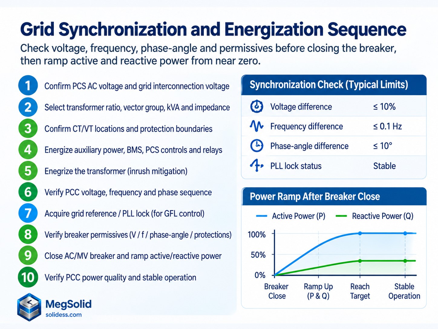
Grid synchronization is not:
“PCS sees 50Hz → breaker closes.”
A utility-approved SLD should not reduce synchronization to that shortcut.
Treat PLL Lock as One Synchronization Permissive
Grid-following PCS uses the PLL to estimate phase and frequency from the measured AC voltage waveform.
The grid reference lets the converter control current relative to the existing grid.
Strong grids usually provide a stable reference for this process.
Weak grids with voltage distortion, phase jumps or frequency instability can make an aggressively tuned PLL part of the instability.
MegSolid se grid-following vs grid-forming PCS engineering covers this weak-grid boundary in more detail.
The SLD must show this control boundary:
PLL lock is only one permissive in the synchronization chain.
PLL lock does not replace protection, breaker interlocks or sync-check logic.
Verify Voltage, Frequency and Phase Angle Before Paralleling
Before a grid-connected source is paralleled to an energized bus, the control and protection scheme must verify the required synchronization conditions.
Check the Three Synchronization Quantities
- Voltage magnitude
- Frequency
- Phase angle
The acceptable window is not a universal ±2%, ±5% or one fixed phase-angle value for every BESS.
Dit hang af van:
- utility requirements
- project size
- protection settings
- interconnection standard
- switchgear logic
- approved commissioning procedure
IEEE 1547 and IEEE 1547.1 establish interconnection and verification requirements for DER systems, but the actual project settings must come from the approved interconnection package.
Never put arbitrary synchronization tolerances into an SLD note just because they appeared in another project.
Close the Breaker Only After All Permissives Are Satisfied
The breaker or contactor should close only after all required permissives are satisfied.
Use a Defined Breaker-Closure Sequence
- auxiliary systems healthy;
- BMS and PCS ready;
- upstream grid available;
- protection relays healthy;
- breaker states confirmed;
- PCC voltage and frequency measured;
- PLL or grid-reference acquisition complete where applicable;
- synchronization / sync-check permissive satisfied;
- breaker closes;
- active and reactive power ramp from near zero.
The final active/reactive power ramp is part of the synchronization sequence.
Do not close onto the grid and immediately command full discharge.
Commissioning should verify:
- voltage
- current
- active power
- reactive power
- power factor
- THDi
- relay status
- breaker timing
- communications
Die BESS site acceptance checklist should capture those events instead of relying on “PCS online” as proof of successful synchronization.
Separate Grid-Following and Grid-Forming Synchronization Logic
These modes are not marketing labels.
They change the electrical behavior of the BESS.
Grid-Following (Grid-Tied) Inverters
Grid-following PCS relies on an existing voltage and frequency reference.
It measures the grid and injects controlled current relative to that reference.
When the grid disappears, the PCS cannot simply continue energizing the same utility-connected bus.
Anti-islanding and protection logic must separate the BESS from the Area EPS.
MegSolid se anti-islanding and grid-tied BESS architecture explains why a charged battery can still shut down during an outage.
Normal grid-tied interconnection often uses GFL as the simpler control architecture.
Weak grids can expose PLL and control-interaction problems that a stiff utility source hides.
Grid-Forming (Virtual Synchronous Machine) Inverters
Grid-forming PCS behaves as a controlled voltage source and can establish voltage and frequency for an islanded bus.
Some implementations use virtual synchronous generator or virtual synchronous machine algorithms.
Grid-forming does not automatically mean VSM, and it does not automatically mean the project can black start.
Treat Black Start as a Full-System Function
Black start requires the full architecture to support:
- dead-bus energization
- transformer energization
- auxiliary power
- protection logic
- load pickup
- voltage control
- frequency control
- available SOC
Grid-forming becomes valuable in:
- microgrids
- weak-grid projects
- intentional islands
- black-start architectures
- systems requiring voltage/frequency support
The mode must be identified on the SLD because it changes how the bus is energized and how protection is coordinated.
Mitigate Transformer Inrush Before SAT
This is where clean design drawings meet ugly commissioning reality.
Model Transformer Inrush Before Energization
Transformers can draw very high magnetizing current during energization.
The magnitude depends on:
- closing point on the voltage waveform
- residual core flux
- transformer design
- source impedance
- transformer size
- protection settings
Peak inrush can reach many times rated transformer current.
Recognize the Commissioning Effects of Inrush
- instantaneous overcurrent trip
- upstream relay operation
- voltage depression
- nuisance protection events
- failed commissioning
Repeated transformer trips during energization do not automatically justify a higher relay setting.
A higher setting may simply hide a coordination problem.
Select an Approved Transformer Energization Strategy
The first step is to model the energization sequence before SAT.
Possible strategies include:
- protection settings coordinated with transformer inrush
- controlled breaker closing
- pre-insertion impedance
- sequential transformer energization
- reduced-voltage energization
- converter-assisted soft energization where the PCS architecture supports it
PCS-assisted gradual transformer energization from the low-voltage side can be effective in some grid-forming architectures.
It is nie a universal BESS commissioning trick.
Confirm the Preconditions for PCS-Assisted Energization
- PCS can establish the dead LV bus;
- PCS voltage ramp is controllable;
- transformer connection is compatible;
- protection allows reverse energization;
- auxiliary systems are powered;
- grounding remains correct;
- MV breaker interlocks prevent unintended paralleling.
PCS-assisted energization sequence: PCS establishes LV voltage → voltage ramps gradually → transformer core magnetizes → MV side reaches controlled voltage → synchronization permissives are checked → MV breaker closes.
Use that sequence only when it is part of the approved control philosophy.
Do not improvise transformer energization during commissioning.
Unplanned energization sequences can leave protection engineers debugging a live plant during commissioning.
Prove the Transformer and Synchronization Sequence on the SLD Before SAT
BESS interconnection is not a copy-paste solar SLD.
It is also not solved by writing “500kW PCS + transformer” on one line and leaving the rest to commissioning.
Utility-ready BESS design must close:
PCS duty → transformer duty → grounding → fault current → protection → harmonics → PCC measurement → synchronization → energization sequence
The MegSolid MEGA PCS gives EPC teams a defined converter platform with bidirectional operation, configurable active/reactive power and low on-grid THDi.
The site SLD must then prove how that PCS connects through the actual project transformer, protection and synchronization system to the POI.
Send the Interconnection Inputs Before Utility Review
Provide MegSolid with:
- preliminary SLD
- PCS power requirement
- battery voltage window
- LV bus voltage
- MV interconnection voltage
- proposed transformer kVA
- transformer impedance
- vector group
- grounding method
- utility protection requirements
- short-circuit data
- GFL or GFM requirement
- black-start requirement
- commissioning sequence
MegSolid can review the interface before the utility review turns one wrong transformer note into another drawing revision.
Do not let the first real synchronization test happen during SAT.
Make the SLD prove the sequence first.
VGV
Is the PCS isolation transformer the same as the project MV step-up transformer?
No. The PCS isolation transformer is part of the converter architecture, while the project MV step-up transformer is selected for the actual grid interconnection voltage, kVA duty, vector group, grounding, impedance, tap range and protection interfaces.
What should be frozen before releasing the BESS single-line diagram?
Freeze the PCS AC voltage, transformer ratio, vector group, grounding, impedance, protection boundaries, PCC measurement, synchronization logic and breaker permissives.
Why must a BESS transformer be checked in kVA instead of kW alone?
A BESS can exchange both active and reactive power, so transformer and switchgear duty must be checked in apparent power as well as real power.
Should a K-13 transformer automatically be specified for BESS projects?
No. K-factor should be based on the actual harmonic spectrum and transformer heating assessment rather than copied from another project.
Does PCS THDi below 3% prove that the entire site passes the harmonic study?
No. A component-level THDi figure does not prove plant-level compliance at the PCC. The complete plant and system impedance still require evaluation.
How does transformer impedance affect a BESS interconnection?
Lower impedance can increase available fault current, while higher impedance increases voltage drop and can affect dynamic response. It must be coordinated with PCS current limiting, switchgear, protection, cables, grounding and the utility source.
What conditions should be checked before a BESS is synchronized to the grid?
Verify voltage magnitude, frequency, phase angle, protection status, breaker states and all required synchronization permissives. PLL lock may be one permissive for grid-following control but does not replace protection or sync-check logic.
Are synchronization limits for voltage, frequency and phase angle universal?
No. The acceptable windows depend on utility requirements, project size, protection settings, interconnection standards, switchgear logic and the approved commissioning procedure.
What happens after the synchronization breaker closes?
Active and reactive power should ramp from near zero, followed by verification of PCC voltage, current, active power, reactive power, power factor, THDi, relay status, breaker timing and communications.
How does grid-following BESS synchronization differ from grid-forming operation?
Grid-following PCS relies on an existing voltage and frequency reference. Grid-forming PCS can establish voltage and frequency for an islanded bus, which changes energization and protection logic.
Does grid-forming automatically mean the BESS can black start?
No. Black start also requires dead-bus energization, transformer energization, auxiliary power, protection logic, load pickup, voltage and frequency control, and sufficient SOC.
Why can transformer inrush cause BESS commissioning failures?
Transformer energization can create high magnetizing current that may cause overcurrent trips, relay operation, voltage depression and nuisance protection events. The energization strategy should be modeled before SAT.
What inputs should be sent for a BESS transformer and grid-integration review?
Provide the preliminary SLD, PCS power requirement, battery voltage window, LV bus voltage, MV interconnection voltage, transformer kVA and impedance, vector group, grounding method, utility protection requirements, short-circuit data, GFL or GFM requirement, black-start requirement and commissioning sequence.