 Yiya kumxholo
At a Philippine factory, high overnight humidity, rain-driven air exchange and rapid temperature changes can push cold cabinet surfaces below the local dew point. An outdoor BESS installation may look dry at shift end and show moisture near gland plates, terminal areas or cooling surfaces the following morning. Because droplets can appear hours after the triggering condition, visual inspection alone cannot determine whether the cause is internal condensation, external water ingress, restricted drainage or an unsuitable control setting.
The Philippine condensation scope extends the Commercial Battery Storage System for Heat, Dust, Salt and Noise pillar into dew-point control, drainage and cabinet acceptance. A MegSolid project review begins with time-aligned air temperature, relative humidity, calculated dew point and cold-surface temperature. PAGASA reports average monthly relative humidity ranging from 71% in March to 85% in September. An “IP54 outdoor cabinet” specification alone does not define how internally formed moisture will be detected, controlled or drained.
Kwabantu abathile ESSA0100B-0215 ikhabhathi yangaphandle, the project review must establish which surfaces can fall below the local dew point, how cable entries and drainage are arranged, and which logged measurements will confirm safe operation through rain, overnight shutdown and restart.
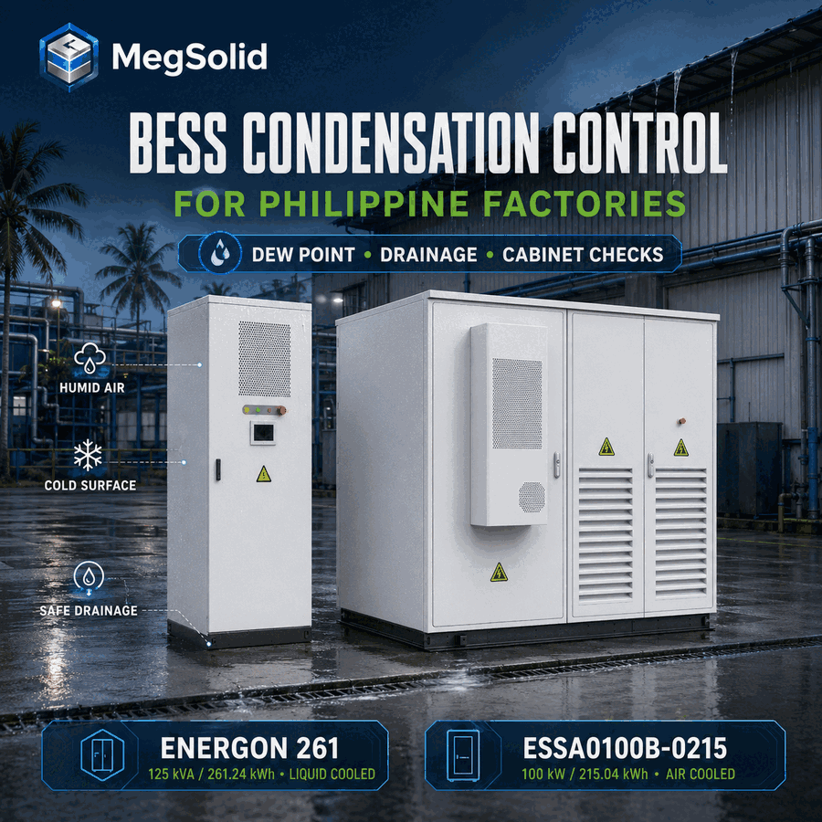
What the purchase file has to lock
- Use temperature, relative humidity and surface-temperature data together. An RH value alone leaves condensation risk unconfirmed.
- Define the coldest credible internal surface for each operating mode.
- Separate external water ingress from water formed inside the enclosure.
- Keep glands, door seals, drain paths and the installation pad in the same inspection scope.
- Require dew-point margin, alarm logic and recovery behaviour in the control narrative.
- Treat “non-condensing” as an operating condition the project has to maintain.
Why Philippine Humidity Changes the Cabinet Design Review
Factories in Metro Manila, CALABARZON, Central Luzon, Cebu and other industrial areas experience different rainfall, wind exposure and local temperature cycles. The common engineering issue combines warm air with high moisture content. Refrigerated areas, air-conditioned electrical rooms, shaded outdoor walls and idle equipment can add cold surfaces to that air.
Condensation risk often shows up in the transition hours, when surfaces lag the air.
| Site event | Moisture mechanism | Cabinet evidence to check |
|---|---|---|
| Warm, humid air arrives after a cool night | Enclosure surfaces remain cooler than incoming air | Outside air temperature/RH, internal surface temperatures, door and vent condition |
| Production stops overnight | Internal heat falls and metal surfaces cool | Shutdown time, fan or cooling state, dew-point margin trend |
| An air-conditioned electrical room is opened to a humid plant | Moist air reaches cold equipment and panels | Room and cabinet temperature/RH on both sides of the transition |
| Heavy rain cools an outdoor cabinet wall | Inner wall or nearby metalwork drops toward dew point | Rain timestamp, wall temperature, internal RH and inspection photographs |
| Washdown or roof runoff reaches cable entries | Liquid enters from outside | Gland, drip-loop, canopy, base and drainage inspection |
| Liquid-cooling equipment runs with an aggressive setpoint | Cold plate, pipe or fitting approaches local dew point | Coolant supply temperature, internal dew point, insulation and leak/condensate evidence |
The scope stays with internal condensation and drainage. Coastal chloride attack has a different inspection and coating scope; that boundary is covered in coastal BESS corrosion protection. The broader heat, dust, salt and noise screen remains in Commercial Battery Storage System for Harsh Sites.
Condensation Starts at the Coldest Surface
Dew point marks the temperature where water vapour in air begins to condense. PAGASA explains the relationship through dry-bulb, wet-bulb, relative-humidity and dew-point measurements, while Schneider Electric's enclosure guidance describes the same field mechanism: warm moist air contacts a surface below the air's dew point.
Condensation risk exists when a cabinet surface temperature ≤ the local dew-point temperature
A ceiling sensor can miss a colder gland plate, door skin, coolant fitting or cable shield near the base. The project should identify the coldest credible surface and place sensors where they can represent the risk.
A 30 °C and 80% RH example
The values below are a worked example. They are not ESSA limits.
At 30 °C and 80% RH, the calculated dew point is approximately 26.2 °C. A metal surface at 28 °C has a positive margin of roughly 1.8 °C. A surface at 24 °C sits about 2.2 °C below the dew point, so water can form even though the surrounding air feels warm.
| Measured or calculated value | Example result |
|---|---|
| Local air temperature | 30 °C |
| Relative humidity | 80% |
| Calculated dew point | Approximately 26.2 °C |
| Cabinet surface A | 28 °C |
| Margin at surface A | +1.8 °C |
| Cabinet surface B | 24 °C |
| Margin at surface B | −2.2 °C |
Dew-point margin = coldest monitored surface temperature − calculated dew-point temperature
A positive value shows how far the surface remains above dew point at that measurement point. The project needs an approved operating margin that covers sensor accuracy, location, control delay and temperature gradients. Do not drop a generic 2 °C or 5 °C margin into the spec until the sensors and cabinet have evidence.
Check a suspected condensation event with time-aligned data
Send 24–72 hours of outside and cabinet temperature/RH readings, the operating-mode timeline, available coolant or fan values, alarm history and photographs of the first wet location. MegSolid can identify the missing measurements and separate a dew-point event from rain ingress or a drain failure.
RH Alone Can Misdirect the Inspection
Relative humidity moves with temperature. The same moisture content reads higher as air cools and lower as it warms. An alarm set only at 80% RH can trip early in one hour and late in another.
The operating record should carry at least four values on one time base:
- 1. Air temperature at the location represented by the RH sensor
- 2. Relative humidity at that same location
- 3. Calculated dew point
- 4. Temperature of the coldest relevant cabinet surface
The control system may calculate dew point in the controller, EMS or site supervisory system. Procurement should confirm the formula, input tags, units, sensor range, stated accuracy, sampling interval and fail-safe response. A dashboard tile that shows “humidity normal” leaves the coldest surface unproven against dew point.
Sensor placement needs the same attention. An RH probe next to a warm PCS outlet will not see the air at a cool door panel. A probe mounted where rainwater, condensate or direct airflow hits it can also give misleading readings. Commissioning should compare portable reference measurements with installed tags at the actual risk locations.
I- Isakhiwo sonxibelelwano se-BMS ne-EMS explains how equipment and site tags should share timestamps. Condensation analysis breaks down when temperature, RH, fan, pump and alarm records come from separate clocks.
Keep IP54 and Non-Condensing Limits in Their Proper Roles
IEC 60529 classifies the degrees of protection provided by electrical enclosures against access, solid foreign objects and water under its defined test conditions. IEC 60529 does not cover moisture already inside the box through every temperature cycle.
The current MegSolid product reference gives the following ESSA0100B-0215 boundary:
| Ipharamitha | Ixabiso elipapashiweyo | Condensation-control meaning |
|---|---|---|
| Amandla ombane we-AC amiselweyo | I-100 kW | Record actual duty because internal heat changes with operation |
| Nominal energy | 215.04 kWh | Energy capacity leaves moisture behaviour undefined |
| Cell data | 280 Ah LFP | Confirm the supplied battery configuration in the controlled BOM |
| Charge/discharge rate | 0.5C at 25 °C | The 25 °C value leaves a hot-humid site unproven |
| Ukubandisa | Ukupholisa umoya okubukrelekrele | Confirm air path, fan states and exposed environmental tags |
| Iqondo lobushushu lokusebenza | 0–45 °C | Project conditions must remain within the controlled operating envelope |
| Relative humidity | 0–95%, non-condensing | The cabinet is specified for high RH only while condensation is prevented |
| Isingxobo | Ipasi-5, i-4 | Preserve doors, seals, glands and service interfaces after installation |
| Monitoring and communications | Touch LCD, cloud platform, RS485 and TCP/IP | Confirm the exact temperature, humidity and alarm tags in the ordered system |
| Ukudityaniswa | Built-in isolation transformer and integrated EMS functions | Use the integrated event history for root-cause review when the required tags are supplied |
“0–95%, non-condensing” means high RH is allowed only while the inside stays dry. Water on terminals at 95% RH is outside that rating.
ESSA's integrated 100 kW / 215.04 kWh architecture can simplify the responsibility boundary: battery, PCS, air cooling, isolation transformer and EMS functions are delivered within one cabinet platform. The advantage remains conditional on the ordered sensors, alarms, seals and drainage details. The 215 kWh outdoor cabinet engineering page provides additional architecture context.
Trace the Water Before Choosing the Remedy
Moisture found inside a cabinet has at least three possible paths. Each path needs a different response.
Water entering from outside
Rain, roof runoff, washdown spray or standing water can enter through a damaged seal, poorly tightened gland, open door, unsealed conduit or incorrect cable approach. Look for a clear wet track from the entry point, water concentrated after rainfall, dirt washed along the path and local damage to a seal or fitting.
Corrective work belongs at the entry path. An internal heater leaves a loose gland or a roof-water cable unrepaired.
Water formed on a cold internal surface
Internal condensation usually follows the temperature geometry. Droplets appear on cool metal, fittings, plates, pipes or components even when the external surface is dry. A trend can show the surface crossing the calculated dew point before the observation.
The remedy can include a control-sequence change, a different cooling setpoint, insulation on a cold component, managed ventilation, approved enclosure heating or dehumidification. The supplied feature set must be confirmed. Do not assume a heater, dehumidifier or dew-point controller from the base ESSA sheet. Name the device on the order and BOM.
Liquid escaping from a cooling or service circuit
On a liquid-cooled system, a wet fitting may be coolant leakage, condensation, or both. Check fluid colour, odour and chemistry through the approved service procedure; inspect pressure and leak alarms; and compare the coolant temperature with the local dew point. Wipe-and-wait does not identify the liquid.
This diagnostic split is part of the Ulondolozo lwe-BESS epholisiweyo ngamanzi scope.
Drainage Must Work With the Installed Cabinet and Pad
Water management extends below the enclosure. A well-sealed cabinet installed on a flat pad with blocked channels can sit in standing water. A cabinet with a drain outlet can still fail when the route rises, kinks, terminates in mud or receives backflow.
The civil, electrical and equipment drawings should agree on:
- Pad elevation above the surrounding finished grade
- Surface slope away from the cabinet and cable entries
- Open drainage routes that remain accessible for inspection
- Cable trenches protected against becoming water reservoirs
- Conduit seals appropriate to the design and local practice
- Drip loops and entry direction that keep runoff away from glands
- Door swing and service access that avoid directing rain into an open compartment
- Roof, canopy and adjacent equipment runoff paths
- Drain outlet size, route, termination and maintenance access, when fitted
- Corrosion-compatible fasteners and hardware at wet locations
Inspect drainage during and after a realistic water event. A drawing review misses a pad poured with the wrong fall or a drain hose crushed during installation.
The distinction between an enclosure rating and the as-built installation should appear in the handover record. The OEM can supply an IP-rated cabinet; the EPC and owner still control pad level, field glands, conduits, trench drainage, cable routing and door discipline.
Air Cooling and Liquid Cooling Create Different Cold Surfaces
Cooling selection changes the condensation map. The dew-point calculation stays.
| Umbuzo weprojekthi | ESSA0100B-0215 | Energon 261.24 kWh platform |
|---|---|---|
| Published thermal method | Ukupholisa umoya okubukrelekrele | Ukupholisa okuthe tyiwa |
| Uluhlu olupapashiweyo | 100 kW / 215.04 kWh | 125 kVA / 261.24 kWh |
| Published temperature range | 0–45 °C | −20–55 °C; derating above 45 °C |
| Published enclosure rating | Ipasi-5, i-4 | Confirm the controlled project datasheet |
| Published RH boundary | 0–95%, non-condensing | Public operating-humidity field is unresolved; request the controlled value |
| Condensation points to examine | Intake air, cool walls, gland plates, air paths and surfaces after shutdown | Cold plates, pipes, fittings, heat exchanger surfaces, insulation terminations and cabinet air |
| Maintenance emphasis | Fans, airflow, seals, sensor placement and drainage | Coolant temperatures, pumps, leak evidence, insulation, dew-point margin and drainage |
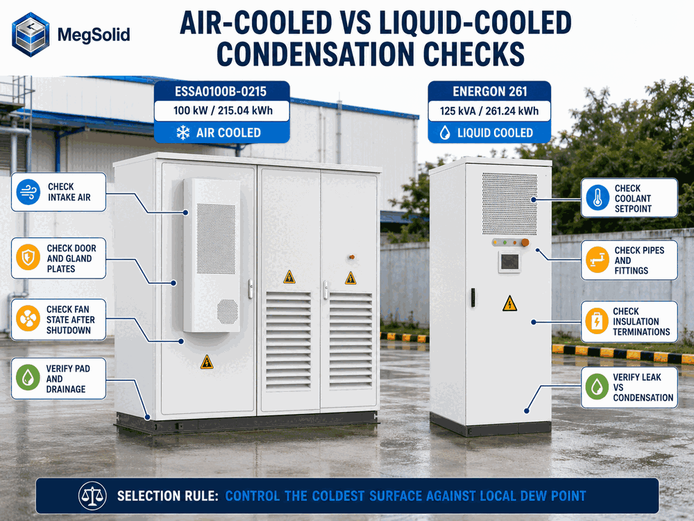
Air-cooled ESSA suits projects where its 100 kW class, 215.04 kWh nominal energy, 0–45 °C published range and serviceable air path fit the site. Energon deserves review where the duty supports a 125 kVA / 261.24 kWh liquid-cooled platform and the project can maintain the cooling loop. The selection needs the as-ordered environmental limits and warranted available power; cabinet capacity alone leaves the selection unsettled.
MegSolid's current Energon page identifies 314 Ah LFP cells. Do not call standard Energon or ESSA hybrid solid-state unless the quote, signed datasheet and BOM name a different cell.
I- Energon liquid-cooled system page kunye ne ESSA outdoor cabinet page should be reviewed against the same site data.
Write the Dew-Point Control Narrative Before FAT
A useful control narrative answers what the cabinet does during operation, shutdown, restart and sensor failure. At minimum, define:
- 1. Temperature and RH inputs used to calculate dew point
- 2. Location and accuracy of each input sensor
- 3. Cold-surface temperature used for the control margin
- 4. Warning threshold, delay and reset behaviour
- 5. Cooling, fan, pump, heater, vent or dehumidifier response where fitted
- 6. Behaviour during grid loss, auxiliary-power loss and communications loss
- 7. Minimum run-on or standby behaviour after charging or discharging stops
- 8. Restart permissive after a low-margin or condensation alarm
- 9. Operator action and escalation path
- 10. Event, trend and alarm retention period
Any optional device must be named. “Anti-condensation control included” is too thin for purchase or testing. The document should identify the heater, dehumidifier, vent, sensor, controller output, auxiliary supply and alarm tag included in the ordered cabinet.
Control action also needs energy and thermal context. Holding a cabinet warm through a shutdown consumes auxiliary energy. Ventilating with humid outside air may raise the dew point. Driving a liquid loop to a lower temperature can improve cell cooling while shrinking the condensation margin around pipes and fittings. The control sequence has to balance these effects at the actual site.
Use FAT for Function and SAT for the Installed Moisture Path
IEC 60068-2-30:2025 describes damp-heat cyclic testing with high humidity and cyclic temperature changes that generally produce condensation on the specimen. A project may use this or another agreed standard as evidence for components or equipment where its scope fits. The report must identify the specimen, configuration, severities, cycles, functional state, acceptance criteria and observed result.
FAT should confirm the cabinet-level functions that can be tested before shipment:
- Environmental sensor identification, range and calibration evidence
- Dew-point calculation or site-controller interface
- Warning, delay, latch and reset logic
- Cooling, fan, pump or optional anti-condensation-device response
- Sensor open-circuit, out-of-range and communications-failure behaviour
- Alarm and trend export with synchronized timestamps
- Door, gland, seal, drain and insulation workmanship against the approved drawings
- Applicable damp-heat or cyclic environmental evidence with the correct model scope
SAT checks the parts created by the installation:
- Cabinet level, anchoring and pad drainage
- Field cable entries, conduit sealing and drip loops
- Canopy, roof runoff, nearby equipment discharge and washdown exposure
- Installed temperature/RH sensor locations
- Communications tags and time synchronization
- Shutdown, standby and restart sequence
- Drain flow and termination where a condensate drain is supplied
- Post-rain and early-morning inspection under agreed safe conditions
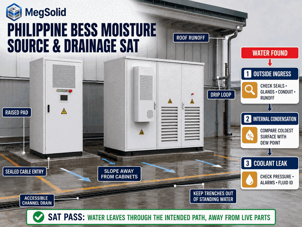
The SAT record needs a clear result. “Humidity checked” leaves the next maintenance team nothing to compare.
Acceptance passes only when the coldest monitored surface stays above the approved dew-point margin, alarms and controls follow the approved sequence, and water leaves through the intended drains, away from live parts
Put These Items Into the Purchase Specification
The environmental schedule should ask for project-specific evidence, not a brochure line. Include:
- 1. Design air-temperature and RH range, including shutdown and restart conditions
- 2. Design dew point and the coldest expected internal surface temperature
- 3. Required dew-point margin and the engineering basis for it
- 4. Sensor model, range, accuracy, position, calibration and replacement plan
- 5. Environmental alarm list, delay, latch, reset and operator action
- 6. Fan, cooling, pump and optional heater/dehumidifier/vent control sequence
- 7. Auxiliary-power requirements during standby and grid loss
- 8. Door, seal, gland, vent, drain and insulation drawings
- 9. IP report and exact enclosure configuration covered by it
- 10. Damp-heat test evidence and exact specimen boundary
- 11. Field drainage, pad, trench and cable-entry responsibility matrix
- 12. Alarm and trend points available to the EMS or SCADA
- 13. FAT test sheet and SAT moisture-path inspection form
- 14. Warranty conditions related to condensation, drainage, field entries and maintenance
- 15. Recovery procedure after detected water or a dew-point-margin alarm
- 16. Controlled datasheet and BOM for the supplied cabinet
The commercial advantage of an integrated platform appears here. A single cabinet supplier can define the interactions among battery, PCS, thermal control, alarms and EMS. The purchase order still needs a complete boundary between OEM work and site work. Otherwise, the first wet gland can start an argument among the cabinet supplier, EPC and civil contractor.
For the wider project boundary, use MegSolid C&I energy-storage engineering together with the project-specific single-line diagram and responsibility matrix.
A Practical Inspection After a Humid Shutdown
Consider a Philippine food-processing plant that stops part of its load overnight. The ESSA cabinet is outdoors under a canopy. The sequence below is an example from site observations. It is not a warranty table.
At 22:00, the cabinet load falls and the internal heat source reduces. At 03:30, rain and wind cool the shaded door skin. At 05:10, outside air is measured at 29 °C and 84% RH, giving a dew point near 26 °C. A gland plate measures 25 °C. At 05:20, the inspection team sees fine droplets near the gland plate but no wet track from the door seal.
The evidence points toward a dew-point crossing at the cold gland plate. The team still checks the gland and cable route before assigning the cause. The corrective review then covers sensor placement, shutdown fan logic, cabinet leakage paths and an approved means of maintaining margin. Do not assume a heater is fitted. If one is used, engineer rating, supply and control first.
On the next comparable event, the record should show whether the approved change kept the gland plate above the specified margin. A dry photograph alone leaves the condition unproven once ambient moisture and surface temperature have moved.
Close the Event With Evidence After the Surface Is Wiped
When moisture is found, the safe response depends on location and equipment state. Personnel must follow the model-specific isolation, lockout, access and inspection procedure. Water near energized parts stays outside routine housekeeping.
The event record should contain:
- Date, time, weather and operating mode
- Cabinet model, serial number and firmware
- Outside and internal temperature/RH values
- Calculated dew point and identified cold-surface temperature
- First wet location and photographs before disturbance
- Rain, washdown, HVAC, fan, pump and coolant timeline
- Door, gasket, gland, cable, conduit, base and drain condition
- Alarm and event export with timestamps
- Fluid identification where coolant leakage is possible
- Authorized drying, repair and inspection steps
- Electrical checks required before re-energization
- Corrective action and verification under a comparable condition
A fault should remain open until the source is supported by evidence and the corrective action is verified. “Cleaned and restarted” leaves the same mechanism ready for the next humid transition.
Condensation Control Protects the Product Advantage
ESSA0100B-0215 brings 100 kW rated AC power, 215.04 kWh nominal energy, intelligent air cooling, IP54, a built-in isolation transformer and integrated EMS functions into one outdoor cabinet platform. For Philippine factories, that integration can reduce interface work and give maintenance one event timeline. Its published humidity range remains explicitly non-condensing.
Energon adds a 125 kVA / 261.24 kWh liquid-cooled route for projects whose duty, temperature and service plan support that architecture. Liquid cooling changes the cold-surface and maintenance map; the project must control coolant temperature against dew point and verify the ordered humidity limit.
For a Philippine factory, the release rule is direct: measure the moisture state, identify the coldest surface, maintain the approved margin, give water a safe route and prove the complete sequence at the installed site.
Confirm the environmental and SAT scope before ordering the cabinet
Provide the Philippine project location, hourly temperature/RH range, installation arrangement, shutdown schedule, cabinet duty, drainage drawing and required AC power. MegSolid will identify the controlled product data, environmental tags, optional devices and acceptance checks that must be fixed before quotation.
Imibuzo Ebuzwa Rhoqo
1. What causes condensation inside a BESS cabinet?
Condensation forms when a cabinet surface falls to or below the local air's dew point. Warm humid air, rapid cooling, shutdowns, rain-cooled walls and aggressive liquid-cooling setpoints can create that condition.
2. Is high relative humidity the same as condensation?
No. Relative humidity describes how close the air is to saturation at its current temperature. Liquid water forms when a surface or the air reaches the dew point. Temperature, RH and surface temperature must be reviewed together.
3. Why is dew point more useful than an RH alarm alone?
Dew point represents the moisture content in a way that can be compared directly with surface temperature. An RH alarm alone cannot show whether a particular metal plate, pipe or terminal surface is cold enough to collect water.
4. Does IP54 prevent condensation inside an ESSA cabinet?
IP54 addresses protection against solid and liquid ingress under the applicable IP test. Internal condensation can still occur when trapped or admitted humid air contacts a surface below dew point.
5. What does “0–95% RH, non-condensing” mean for ESSA?
It means the published RH range applies while the environment remains free of condensation. It does not permit water droplets on internal electrical surfaces at 95% RH.
6. Where should temperature and RH sensors be placed?
Place them where they represent incoming or cabinet air and the identified risk zones. Add surface-temperature measurement at the coldest credible location. Final positions should come from the thermal and moisture-path review.
7. Can an outdoor cabinet condense internally even when it does not leak rainwater?
Yes. Moisture already inside the air volume can condense after an enclosure wall, gland plate or cooling component drops below the local dew point.
8. How can the team tell rain ingress from condensation?
Rain ingress often leaves a path from a seal, gland, conduit or runoff point and correlates with rainfall. Condensation tends to follow cold-surface geometry and a recorded dew-point crossing. Both paths should be checked before closing the event.
9. Does liquid cooling remove condensation risk?
No. Liquid cooling can create cold plates, pipes and fittings that need dew-point control and insulation. The coolant setpoint, internal moisture condition and cold-surface temperature must be coordinated.
10. Does ESSA include a cabinet heater or dehumidifier?
The current base product data does not confirm either feature. Any heater, dehumidifier, membrane vent or dedicated dew-point controller must be identified in the ordered configuration, BOM and control narrative.
11. What should happen after a condensation alarm?
The approved sequence should define alarm delay, equipment response, restart permissive, operator action and inspection. The site must preserve trend and event data before resetting the alarm.
12. Should a factory test the cabinet with humidity cycling?
Project requirements may call for applicable damp-heat or cyclic evidence. The report must match the supplied specimen and configuration. SAT still has to verify the field glands, pad, drains, cables and operating sequence.
13. What drainage details belong in the EPC scope?
Include pad elevation and slope, trench drainage, conduit seals, cable entry direction, drip loops, runoff paths and any cabinet condensate drain route. Responsibility for each item should be named.
