
Four MegSolid 5000INTL battery blocks provide 10.8 MW and 20.0636 MWh of nameplate energy. Developers promising 10 MW for two hours at an Australian point of interconnection (POI) have just 63.6 kWh above the energy target before losses. Check whether that margin covers delivery before ordering the containers, PCS and transformers.
The standard block ratio is close to two hours. Four-hour delivery at the same POI power needs more battery energy, though buying more complete blocks also adds PCS capacity.
Smaller network batteries can start with the 500 kW / 1.0752 MWh and 1 MW / 2.1504 MWh MegSolid systems. Queensland’s 260 MW / 1,216 MWh Supernode Stage 3 shows the same power-to-energy mismatch at another scale, and the Supernode equipment calculation separates its confirmed project figures from the MegSolid sizing example.
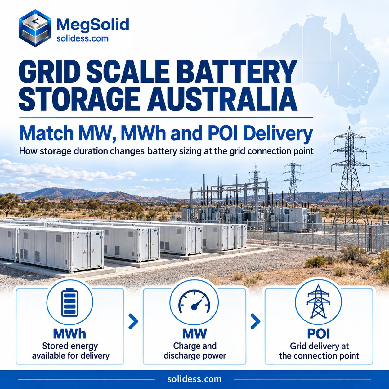
5000INTL sizing for two-hour POI delivery
MegSolid 5000INTL suits an initial assessment of plants built from repeatable, liquid-cooled blocks for a duty close to two hours. Each unit has 5.0159 MWh of rated energy and 2.7 MW of rated AC power at 690 Vac: about 1.86 hours on a nameplate basis.
Compare that ratio with the contract’s required duration to decide whether to size battery energy and PCS power separately.
Consider a 10 MW / 20 MWh project:
| Selection check | Berekening | Result |
|---|---|---|
| Units required by power | 10 MW ÷ 2.7 MW | 3.70 → 4 units |
| Units required by energy | 20 MWh ÷ 5.0159 MWh | 3.99 → 4 units |
| Four-unit nameplate | 4 × 2.7 MW and 4 × 5.0159 MWh | 10.8 MW / 20.0636 MWh |
| Energy above the 20 MWh target | 20.0636 − 20 MWh | 0.0636 MWh, or 63.6 kWh |
The four-unit energy margin is 0.32%. Cooling and controls draw from it, as do conversion and transformer losses before energy reaches the grid meter. The delivery calculation must also exclude capacity outside the operating SOC window and allow for capacity fade over the project life.
Five complete blocks raise the plant to 13.5 MW / 25.0795 MWh. The extra energy provides more delivery margin but comes with another 2.7 MW of PCS capacity. At a 10 MW POI, that conversion capacity needs a defined use, such as redundancy or another contracted duty, to justify its cost.
Check the two-hour option against the delivery test before fixing the block count. Longer discharge periods change how much battery energy is needed per MW of PCS power.
Four-hour delivery needs more energy at the same POI power
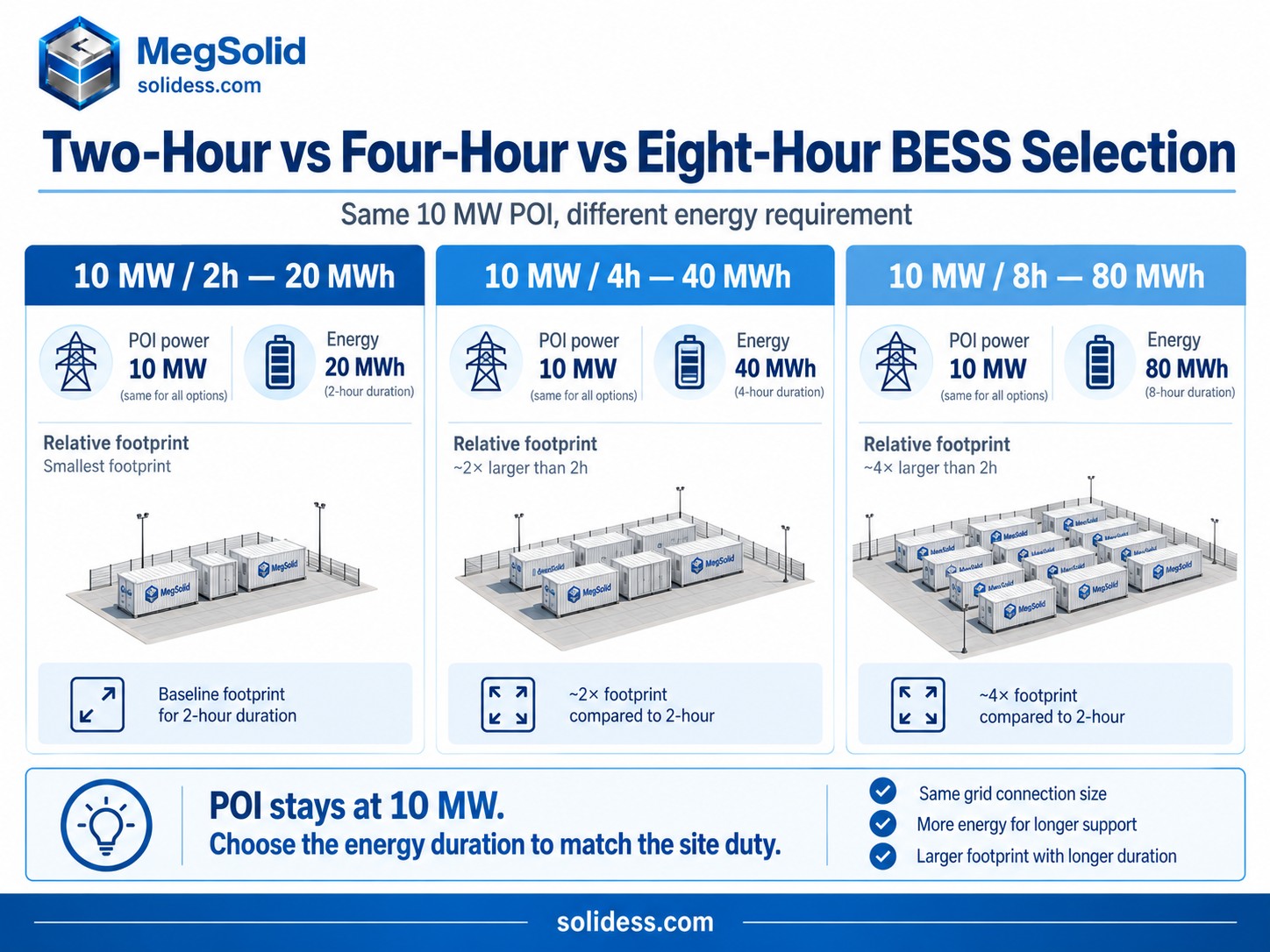
Extending a 10 MW discharge from two hours to four requires twice the energy. Buying complete integrated blocks to reach that MWh target also increases PCS power, even though the connection limit stays at 10 MW.
Australia’s Capacity Investment Scheme Tender 8 selected 15 battery projects totalling 4.2 GW / 16.1 GWh. The combined figures equal about 3.83 hours, and the federal announcement described the portfolio as sufficient to cover the evening peak of 3.7 million NEM households for four hours. Roughly AUD 6 billion of private investment is expected to follow the awards. (Australian Government, CIS Tender 8)
The same tender includes different storage durations. Bulabul 1 is 300 MW / 600 MWh, while Gelston is 400 MW / 1,600 MWh and Moorabool is 300 MW / 1,200 MWh. Each project’s connection and offtake requirements determine its equipment sizing.
At a fixed 10 MW POI, sizing complete 5000INTL blocks by energy gives these quantities:
| Delivery duty | Required energy | Complete 5000INTL blocks by energy | Aggregate block power | Procurement consequence |
|---|---|---|---|---|
| 10 MW for 2 hours | 20 MWh | 4 | 10.8 MW | Standard power and energy ratios are close |
| 10 MW for 4 hours | 40 MWh | 8 | 21.6 MW | 11.6 MW of listed PCS capacity sits above the POI limit |
| 10 MW for 8 hours | 80 MWh | 16 | 43.2 MW | Energy-first selection buys over four times the required AC power |
The 10 MW example keeps the arithmetic easy to follow. Use the same equations for larger POIs, with equipment grouping, the MV collector, main-transformer redundancy and the grid-forming path designed for the larger plant.
Eight complete blocks bring listed PCS power to 21.6 MW in the four-hour case. Check how much of that converter capacity the transformer path can use. POI losses also increase the battery energy required; additional PCS power cannot supply missing MWh.
Supernode Stage 3 in Queensland provides a larger comparison. Its 260 MW / 1,216 MWh rating equals 4.68 hours and contains 176 MWh above a simple 260 MW × 4 hour block. The purpose of that headroom depends on the project’s usable SOC, losses, degradation, availability and service requirements. It is not a universal sizing percentage.
RWE’s Limondale battery in New South Wales has 100 MW registered charging power, 50 MW discharge power and at least 400 MWh of storage. Its eight-hour discharge duty uses a larger charging path. The equipment schedule needs separate entries for charge MW, discharge MW and stored MWh. (RWE Limondale BESS)
Projects targeting 10 MW at the POI and 40 MWh of delivery need a quotation that separates stored energy from AC conversion before complete block quantities become the commercial baseline.
MegSolid options for different connection sizes
The network’s accepted power block and the contract’s energy window guide MegSolid selection. Smaller distribution projects may need a lower-power feeder. Longer-duration plants need more MWh without a matching increase in conversion capacity.
| Projektoestand | MegSolid starting route | Gepubliseerde beoordeling | Why the route fits |
|---|---|---|---|
| Multi-megawatt plant near two hours | 5000internasionaal | 2.7 MW / 5.0159 MWh | One repeatable liquid-cooled block puts battery energy and AC power in the same equipment schedule |
| Smaller distribution-connected FTM battery | ESSC0500B-1075 | 500 kW / 1.0752 MWh | Lower feeder power supports staged projects without starting from a 2.7 MW block |
| One-megawatt distribution project | ESSK1000B-2150 | 1 MW / 2.1504 MWh | One system creates a nameplate period just above two hours |
| Project that must allocate PCS power separately | MEGA0500TS PCS | 500 kW rated / 550 kVA maximum | Converter quantity can be studied against active and reactive power instead of following battery-container count |
MegSolid equips the 5000INTL with smart liquid cooling for the 5.0159 MWh block, an IP55 enclosure, AI-supported early warning and three-dimensional protection. Check cooling performance under repeated dispatch and whether operators can locate alarms among the parallel units.
The two ESSC models suit projects that connect at a lower power level or expand in planned stages. ESSC0500B-1075 uses a 500 kW / 1.0752 MWh configuration; ESSC1000B-2150 doubles both values to 1 MW / 2.1504 MWh. Both use temperature-controlled air cooling and IP54 enclosures. Feeder capacity and the transformer arrangement help determine the choice, along with the planned installation stages. The comparison also needs to show how much plant capacity is lost when one block is out for maintenance.
Assess MEGA0500TS where the project requires separate PCS sizing. Its 500 kW rated output, 550 kVA maximum output and 500–850 V DC range let the engineer study real power, reactive headroom and battery voltage together. The MegSolid MEGA TS PCS-reeks also includes smaller power classes, allowing a project to choose conversion power around its electrical duty instead of treating one container as the smallest design step.
Compare costs at the same POI duty. Cycling, auxiliaries, the degradation allowance and the replacement strategy affect lifetime delivered energy, which is the basis of the BESS lifetime cost per delivered kWh method.
The transformer path determines what reaches the POI
Container quantities depend on where the project measures acceptance. In a front-of-meter plant, conversion losses and site loads between the battery and the network-facing meter reduce delivered energy.
The plant needs an electrical path to the POI, with controls and metering for the combined output:
- 1. Battery blocks holding DC energy and enforcing cell operating limits.
- 2. PCS equipment controlling charge, discharge and reactive response.
- 3. Unit transformers raising the converter output to the collector voltage.
- 4. Collector feeders and switchgear grouping blocks into protected zones.
- 5. Main transformer and POI equipment carrying the complete plant into the network.
- 6. Plant controller and revenue metering turning the connection limit into a measurable operating target.
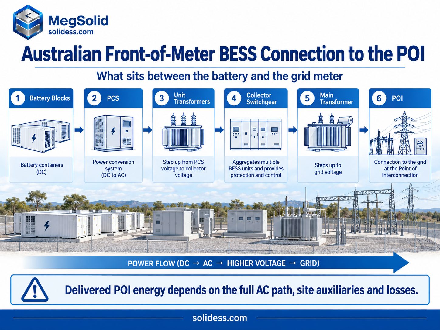
MegSolid 5000INTL supplies rated AC power at 690 Vac. An Australian grid-scale battery will place that output behind the transformer and collection arrangement selected for the site. The POI voltage, export limit, charging limit and reactive duty then decide how much of the combined 2.7 MW blocks can operate at once.
Ten 5000INTL blocks provide 27 MW of rated AC power, which exceeds a 25 MVA transformer path even at unity power factor. Reactive demand uses additional MVA capacity. The loading study must account for kW, kvar and kVA at the transformer temperature, tap position, contingency and control mode being assessed.
Switchgear must accommodate the voltage and continuous current in both directions. Its short-circuit duty, protection selectivity and isolation arrangement also need verification. The BESS switchboard connection method explains these checks at low voltage, and the same logic continues through the medium-voltage collector and substation equipment of a larger plant.
Market location also changes the project boundary. NEM projects work through AEMO and the relevant network connection process, while Western Australian projects operate under WEM and local network arrangements. The AEMO Integrating Energy Storage Systems project shows how bidirectional storage is treated across registration, dispatch and metering. Container pricing needs to be based on the identified market, network and POI.
Dispatch schedules and competing services
Evening delivery, wholesale trading and rapid FCAS response can require different SOC allowances from a plant with the same MW and MWh ratings. Use the dispatch schedule to calculate thermal duty, annual throughput and reserve.
- CIS or contracted evening delivery reserves energy for a named interval. End-of-life MWh and POI availability carry more weight than the ability to chase every short price movement.
- Wholesale arbitrage increases charge and discharge activity around changing spreads. The operating model needs realistic efficiency, auxiliary consumption and cycling assumptions.
- FCAS participation uses fast control response and can move the battery repeatedly around its SOC target. Power capability matters, but the EMS also needs enough energy room to avoid blocking the next instruction.
- Network support binds availability to a location, time window and control interface agreed with the network. Missing the window can matter more than total annual energy.
- Solar or wind firming links battery charging to renewable output, curtailment and the shared export ceiling. Available charging energy can become the limiting input even when the battery has empty capacity.
Gridcog’s Australian comparison found different revenue and operating patterns between modeled NEM and WEM assets. Wholesale volatility supported the NEM FTM case, while the WEM model included capacity credits. Use a project dispatch trace to establish cycling depth and frequency, and assign priority to services that compete for the same capacity. (Gridcog FTM and BTM analysis)
Check the dispatch trace against the 5000INTL’s 1.86-hour nameplate ratio, warranted operating window and throughput terms. Schedule maintenance around contracted availability, and review liquid-cooling performance and early-warning functions for repeated operation across the array.
Evening delivery can require energy to remain in the battery just as an arbitrage opportunity calls for discharge. FCAS headroom can also compete with a full 10 MW export schedule. Renewable firming adds a charging constraint: low wind or cloud cover may remove the expected charging window. The operating model needs priorities and reserves for these conflicts before the revenues are combined.
PCS response in the Australian connection study
Australian connection studies examine how the complete plant responds to active-power commands, reactive demand and disturbances, including interactions among converters under one plant controller. The study scope covers:
- active-power control, ramp rates and charge/discharge limits;
- reactive-power capability across the planned operating range;
- voltage and frequency response;
- fault ride-through and current-priority logic;
- harmonic performance at the POI;
- coordination between PCS units and the plant controller;
- protection response and communications-loss behaviour.
MEGA0500TS provides 500 kW rated output, 550 kVA maximum output, a 500–850 V DC range and 97.5% maximum efficiency. Use the 550 kVA maximum when examining active and reactive capability, subject to the approved operating limits. The final P/Q envelope must match the selected operating point, transformer rating and network requirement.
Harmonics also belong at the grid-facing boundary. Cable length, transformers, background distortion and interaction among parallel converters can change the result between PCS terminals and the POI. The BESS power-quality acceptance method ties kW, kvar, power factor and harmonic measurements to one meter, one operating state and one time record.
AEMO requires connection models to represent the operating plant. The R1 package supports commissioning, while validated R2 data records the final settings and tested response. Converter model, controller version, transformer data and current limits should remain aligned from the connection study through factory configuration and site testing. (AEMO-modelleringseise)
Grid-forming operation adds another decision. ARENA reported in November 2025 that five supported grid-forming batteries had connected to the NEM, and the early projects showed how control models and negotiated performance standards influence delivery. Supernode Stage 3 later placed grid-forming PCS, plant controls, integration and grid-connection support inside GE Vernova’s scope. (ARENA grid-forming battery review)
The PCS, plant controller and connection model must agree on grid-following or grid-forming behaviour. The selected 5000INTL energy block then needs to be assessed within that configuration. The grid-following and grid-forming control explanation shows why stored energy and AC voltage control must be treated as separate capabilities.
Delivered MWh at the contract meter
The delivered-MWh requirement needs a named meter and contract year. Starting from battery nameplate energy, the calculation accounts for the PCS, transformers, collector system and plant auxiliary consumption.
Calculate POI energy in this order:
Installed battery energy → usable SOC window → retained capacity → PCS output → transformer and collector losses → POI energy
Cooling pumps, controls, fire systems, heaters and substation loads also draw energy during the delivery interval. Their treatment must match the project’s metering and acceptance method. In the four-unit 10 MW / 20 MWh example, auxiliary consumption draws from the 63.6 kWh nameplate margin alongside other losses.
MegSolid lists 87.5% as the 5000INTL maximum efficiency. Use that value at its stated equipment boundary. Before including it in a project round-trip-efficiency calculation, establish which charging and discharging losses it covers so they are not counted twice. The POI model needs separate values for the battery path, converter, transformers, collector and auxiliaries under the planned power and temperature.
Waratah Super Battery shows the commercial effect of the AC path. The New South Wales plant has a physical rating of 850 MW / 1,680 MWh and a guaranteed capability of at least 700 MW / 1,400 MWh. High-voltage transformer failure restricted operation during commissioning; Akaysha reported 700 MW online in June 2026, with High Voltage Transformer 3 required for full 850 MW plant capacity and complete 700 MW SIPS service. (Akaysha Energy, Waratah update)
Include transformer availability in the MegSolid delivery guarantee. Even with cells and PCS equipment ready, the plant needs an operating transformer path to deliver at the POI.
Distinguish these energy values in the procurement schedule:
- Rated energy: the installed battery nameplate.
- Usable energy: the portion available inside the approved SOC and operating limits.
- Beginning- and end-of-life delivery: the usable result in the named contract year.
- POI energy: the AC MWh crossing the agreed meter after the project’s losses and auxiliaries.
Apply the operating window, ageing, losses and availability allowances to the 5.0159 MWh per 5000INTL block. Compare the remaining POI energy with the contract test requirement before deciding whether to add capacity.
Container access, fire response and delivery
The available land must accommodate more than the containers. Fire access, drainage and maintenance clearances take space, while the delivery route can limit where equipment can be placed.
MegSolid publishes 5000INTL dimensions of 6,058 × 2,438 × 2,896 mm. Repeating that footprint across a large array gives the civil designer an early basis for rows, cable routes and service access. Obtain the final transport drawing, lifting points, foundation loads and equipment clearances before fixing roads, pads and crane positions.
AFAC’s 2025 guidance asks Australian grid-connected BESS developers to prepare an overall fire-safety strategy and engage the fire and emergency service responsible for the project area. Fire response and possible water inundation both influence the site. The layout needs to show how crews approach an incident, isolate equipment and manage runoff without crossing an unsafe electrical zone. (AFAC large-scale BESS guidance)
The civil and emergency-response teams should confirm vehicle access to the response zones and a route for removing an isolated block after energisation. Map firewater and contaminated-runoff paths, then assess smoke and heat exposure to adjacent blocks and neighbours under prevailing winds. Check the port, road route, laydown area and crane against the planned delivery sequence.
Review the 5000INTL’s IP55 enclosure, smart liquid cooling, AI-supported early warning and three-dimensional protection against the supplied evidence. Incorporate the equipment controls into the Australian site strategy for spacing, detection, emergency isolation, drainage and local response.
Port of Newcastle illustrates the logistics scale behind current projects. It became the first port in New South Wales approved to store grid-scale lithium-ion battery systems at its terminal and had staged equipment for Tomago, Eraring and Bellambi Heights by July 2026. Tomago alone is expected to use over 400 battery units. (Port of Newcastle BESS staging)
Arrange temporary storage, road permits and crane access around the container dimensions and arrival batches. Confirm the route before ordering so access problems do not hold up completed containers.
Brownfield power-station sites and locations near load centres can offer valuable connection infrastructure, but they introduce buried services, old foundations, constrained access and live-system interfaces. Use the MegSolid dimensions for the first layout, then confirm the block count through civil, electrical and emergency planning.
Australian delivery boundary
- Connection models: MegSolid supplies the equipment and PCS inputs agreed in the contract; the Australian connection applicant and its consultant integrate the plant model, complete GPS studies and manage network/AEMO acceptance.
- Warranty energy: the signed schedule must identify rated DC energy, usable DC energy or delivered AC energy at the POI; the standard 5.0159 MWh figure is rated energy.
- Site service: support is coordinated from MegSolid’s Hong Kong/Huzhou locations; Australian attendance must be assigned in the contract to factory dispatch or a named local EPC/partner.
- Chemistry and fire review: assess 5000INTL as SHS180-314, 12P416S Hybrid Solid-State LFP with smart liquid cooling and three-dimensional protection; the Australian fire strategy must use the supplied cell/system evidence and the actual site design, not a generic LFP label.
Taking the selected configuration into detailed design
Use the same equipment assumptions and POI power and energy duty for transformer sizing, the connection study and the site layout. Settle these decisions before detailed design:
| Projektoestand | MegSolid route to carry forward | Decision that must already be settled |
|---|---|---|
| Multi-megawatt duty near two hours | Standard 5000INTL blocks | POI energy margin covers usable SOC, losses, auxiliaries and the required contract year |
| Four-hour or eight-hour duty | 5000INTL energy blocks assessed with a project-specific battery-to-PCS ratio | Converter quantity is based on POI power, not copied from the energy-block count |
| 500 kW distribution-connected plant | ESSC0500B-1075 | Feeder, transformer, protection and operating duty suit 500 kW / 1.0752 MWh |
| 1 MW distribution-connected plant | ESSK1000B-2150 | The network path and staging plan suit 1 MW / 2.1504 MWh |
| PCS power selected separately | MEGA0500TS or another MEGA TS power class | DC voltage, kW, kVA, reactive duty and transformer loading agree |
| Grid-forming obligation | Selected energy block plus a PCS and controller route proven in the connection model | Required response, model versions and commissioning evidence are defined |
| Solar or wind sharing the POI | AC- or DC-coupled arrangement under one plant limit | Charging source, curtailment, metering and controller priority are fixed |
Define where the solar and battery power paths connect. The AC-coupled and DC-coupled battery comparison explains how that choice changes conversion equipment and control. Check the selected arrangement against the shared export ceiling and approved connection model.
Use MegSolid’s published 5.0159 MWh / 2.7 MW ratings for the initial block count and layout. The quotation should show how that count meets the POI duty, including the delivery margin, PCS allocation, 690 Vac connection, cooling and enclosure requirements.
Minimum email data pack
- Send: Australian state, POI charge/discharge MW, delivered MWh, duration, beginning- or end-of-life obligation, connection voltage, operating duty and whether grid-forming response is required.
- MegSolid returns: a preliminary product route, 5000INTL block count or alternative PCS range, the sizing assumptions used and the connection/site items that remain project-specific.
VGV
How many 5000INTL units are needed for a 10 MW / 20 MWh battery?
Four units provide 10.8 MW / 20.0636 MWh of nameplate capacity. That leaves only 63.6 kWh above the energy target before usable SOC, conversion losses, auxiliaries and ageing. Verify the additional margin needed for POI delivery.
Is the standard 5000INTL a four-hour battery block?
Its 5.0159 MWh rated energy and 2.7 MW rated AC power give a nameplate duration of about 1.86 hours. Four-hour projects need a different battery-to-PCS ratio instead of adding complete integrated blocks by energy alone.
What does the 5000INTL maximum efficiency of 87.5% mean for sizing?
Use 87.5% only at the equipment boundary defined for that value. Project RTE and delivered POI energy require a complete loss model covering the battery path, PCS, transformers, collector system, auxiliaries, power level and temperature.
Which MegSolid product fits a smaller front-of-meter battery?
ESSC0500B-1075 provides 500 kW / 1.0752 MWh, while ESSC1000B-2150 provides 1 MW / 2.1504 MWh. Feeder capacity, transformer arrangement, maintenance block size and planned expansion decide between them.
Should an Australian BESS be sized from container MWh or POI MWh?
Start from the MWh required at the contracted POI meter. Container nameplate energy is an upstream design value; usable SOC, retained capacity, losses and auxiliaries determine how much reaches the network.
When should battery energy and PCS power be selected separately?
Separate the decisions when the required delivery period differs from the standard block ratio, when charging and discharging power are asymmetric, or when reactive duty changes the required PCS kVA.
Does every Australian grid-scale battery need grid-forming PCS?
No. Network location, system-strength conditions, connection studies and contracted services determine the control requirement. Grid-forming projects should lock the PCS model, plant controller and evidence path before the connection design is released.
Can a grid-scale battery share a POI with a solar farm?
Yes, when the controller coordinates solar output, battery charge and discharge, curtailment and the shared export limit. AC or DC coupling changes where the power paths meet but does not remove the POI ceiling.
Why can the main transformer limit a fully available BESS?
The battery blocks may be ready while transformer MVA, temperature, reactive demand or an outage restricts grid-facing MW. Transformer rating and redundancy must support the same operating points promised at the POI.
How does the 5000INTL support Australian site operation?
The unit combines smart liquid cooling, IP55 enclosure protection, AI-supported early warning and three-dimensional protection with a defined 5.0159 MWh / 2.7 MW block. Site-level fire access, drainage, emergency isolation and response planning complete the installation.
What changes for a grid-scale battery in the NEM?
NEM projects coordinate registration, dispatch, metering and connection performance through AEMO and the relevant network service provider. POI limits, GPS, model packages and commissioning results become part of the equipment decision.
What changes for a front-of-meter battery in Western Australia?
WEM participation and the local network process shape revenue, dispatch and connection requirements. Capacity credits may affect the commercial model, while equipment sizing must follow the project’s actual operating trace and network boundary.
What do Queensland and New South Wales battery projects show buyers?
Queensland’s Supernode highlights long-duration power-to-energy ratios and grid-forming integration. New South Wales projects such as Limondale and Waratah show how asymmetric power, transformer availability and the POI path can change deliverable performance.