
An EV charging project can have a sound traffic forecast and still stall at interconnection when the combined charger rating exceeds the transformer’s remaining capacity.
MegSolid works with EPCs and charging-site developers to size battery energy storage around the actual point-of-connection limit, charging concurrency, first-hour demand and recharge window.
This guide explains how to size a BESS for EV charging stations at public fast-charging hubs, fleet depots, highway sites and commercial facilities.
The procurement mistake is usually not selecting the wrong battery chemistry. It is treating charger nameplate power, BESS power and battery energy as interchangeable values.
A 215kWh cabinet may contain enough energy for a short charging peak but still lack the AC power required to support several chargers simultaneously.
Conversely, a high-power PCS with insufficient battery capacity may meet the first vehicle surge and then force later drivers to charge at a reduced rate.

Size BESS Power and Energy Separately
The BESS must pass two independent tests:
- Test de puissance : Can the PCS cover the instantaneous difference between charger demand and the power allowed from the grid?
- Test énergétique : Can the battery sustain that difference through the first-hour surge and the site’s design-day charging profile without reaching its minimum SOC?
The U.S. Department of Energy notes that DC fast chargers can operate at outputs up to 500kW, while actual power varies by vehicle and SOC. See its official EV charging station guide.
Battery buffering imports power at a controlled rate, stores it between sessions and supplies the portion of charger demand above the permitted grid-import level.
The DOE’s EV charging battery-storage help sheet identifies grid constraints, peak-demand reduction and short-term resilience as use cases, while warning that an undersized battery can deplete and reduce charging power.
Before specifying equipment, EPCs should review the broader achat de stockage d'énergie commercial framework so that the battery, PCS, EMS, switchgear, transformer and commissioning scope remain under clear responsibility.
Data Required Before an EV Charging BESS Can Be Sized
An RFQ that only states “two 150kW chargers and one 215kWh battery” is not design-ready. EPCs need these inputs:
| Contribution technique | Pourquoi est-ce important ? | Minimum evidence |
|---|---|---|
| Transformer rating and present peak load | Establishes remaining site capacity | Transformer nameplate, one-line diagram and interval meter data |
| Utility import limit | Defines maximum power at the PCC | Utility approval and protection requirements |
| Charger power and concurrency | Establishes simultaneous EV demand | Charger datasheet and session forecast |
| First-hour and design-day demand | Tests the initial surge and battery recovery | Time-series charging profile |
| Facility base load | Uses the same transformer capacity | At least 15-minute interval data |
| PV or generator profile | May support charging but is not always firm | Time-aligned generation data |
| Tariff | Determines peak-shaving value | Demand charge and time-of-use periods |
| Backup requirement | Changes switchgear and reserve SOC | Critical ports and required outage sessions |
Utilisez le Liste de contrôle pour l'acquisition d'un système de stockage d'énergie par batterie (BESS) C&I to verify that the RFQ also defines warranty, FAT, installation environment, documentation and commissioning responsibility.
Convert charger output, transformer capacity, PCS power and auxiliary consumption to the same AC boundary at the point of common coupling.
Use concurrency and a time-series profile rather than either the sum of every charger nameplate or a daily average that hides clustered arrivals.
EV Charging BESS Power-Sizing Formula
At the common AC boundary, screen minimum discharge power as:
PBESS,AC ≥ PEV,concurrent + Psite − Pgrid,allowed − PPV,firm
The variables represent simultaneous EV demand, other site load, approved grid import and dependable PV during the studied event. For an evening or low-irradiance case, set firm PV to zero.
The selected PCS must also satisfy voltage, phase, frequency, current, short-circuit contribution, protection coordination, harmonic and reactive-power requirements.
Critique PCS and inverter engineering before matching a battery solely to charger kW.
EV Charging BESS Energy-Sizing Formula
Integrate the power deficit across the studied event:
Ebuffer = ∫ max[0, Pload(t) − Pavailable(t)] dt
Convert delivered energy into nominal capacity:
Enominal ≥ Ebuffer ÷ (ηdischarge path × usable SOC window × EOL SOH factor)
Include auxiliary loads, temperature derating, recharge limits and repeated sessions before the battery can recover. The NREL-developed “First Hour” and “Design Day” criteria in the DOE-hosted help sheet are useful screens, but they do not replace a local utility study or time-series simulation.
Worked Example: Why 215kWh Does Not Automatically Support Two 120kW Chargers
Consider an illustrative commercial charging site with the following design event:
| Saisie | Valeur illustrative |
|---|---|
| DC charger ports | 2 × 120kW |
| Simplified simultaneous demand at the common boundary | 240kW |
| Utility import limit | 120kW |
| Facility base load | 30kW |
| Firm PV credited during event | 0kW |
| High-demand duration | 45 minutes |
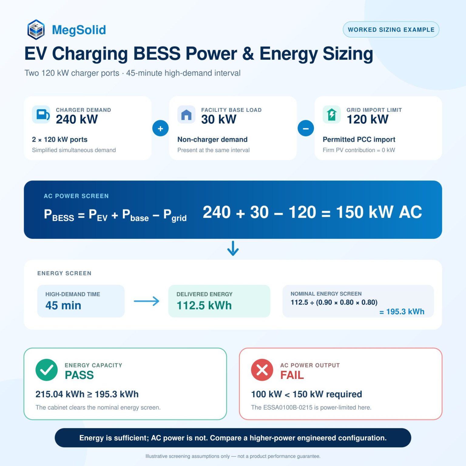
For this preliminary screen, the 240kW demand is normalized to the common AC boundary; a detailed design must add the actual charger loss map. The grid has only 90kW available for charging after serving the facility load. The BESS power requirement is therefore:
240kW + 30kW − 120kW = 150kW AC
During a 45-minute event, the BESS must deliver approximately:
150kW × 0.75 hour = 112.5kWh
If the preliminary model assumes 90% discharge-path efficiency, an 80% usable SOC window and an 80% end-of-life SOH factor, the nominal energy screen becomes:
112.5 ÷ (0.90 × 0.80 × 0.80) = 195.3kWh nominal
This example exposes the procurement trap. A 215.04kWh cabinet appears to pass the preliminary energy calculation, but a cabinet rated at 100kW AC does not pass the 150kW power requirement.
The project therefore requires a higher-power or engineered multi-cabinet architecture, or a control strategy that limits simultaneous charger output. Parallel operation, protection, charger ramp rates and low-SOC behavior must be validated rather than assumed.
The efficiency and reserve factors above are illustrative assumptions, not MegSolid product specifications or a guaranteed project result.
When the MegSolid ESSA0100B-0215 Is a Suitable Starting Point
Le Série d'armoires d'extérieur MegSolid ESSA includes the ESSA0100B-0215.
Its current parameter table identifies LFP cells and intelligent air cooling. The ESSA0100B-0215 platform can also be configured with solid-state battery cells according to project requirements. It is not a liquid-cooled cabinet. The exact cell model and electrolyte architecture must be confirmed in the project-specific quotation, signed datasheet and BOM.
| ESSA0100B-0215 parameter | Current listed value | EV charging design implication |
|---|---|---|
| Puissance nominale en courant alternatif | 100 kW | Candidate where the required AC buffer is no greater than the validated operating limit |
| Puissance nominale | 215,04 kWh | Must be derated for usable SOC, conversion losses and end-of-life capacity |
| Configuration de la batterie | 1P240S | Nominal DC voltage is 768V |
| Charge/discharge rate at 25°C | 0.5C | Duty cycle and recharge interval still require simulation |
| Refroidissement | Refroidissement par air intelligent | Airflow, dust loading and ambient temperature must be assessed |
| Température de fonctionnement | 0–45 °C | Sites outside this range require a different selection or engineered environmental control |
| Annexe | IP54 | Does not replace site drainage, corrosion and impact-protection design |
| Grid-current THD | <3% | Confirm at the project operating point and during FAT |
| Communications | RS485 and TCP-IP | Signal mapping with EMS and charger controls remains project-specific |
The product page lists at least 5,000 cycles without complete comparison conditions. Request the controlled test conditions, warranty throughput and remaining-capacity criterion.
One cabinet may be a candidate where the calculated grid deficit remains below 100kW and the battery can recharge between sessions. It is not a universal match for a 150kW or 240kW charger merely because its energy exceeds one vehicle session.
Preliminary Product Selection Path
| Calculated AC buffer requirement | Preliminary product direction |
|---|---|
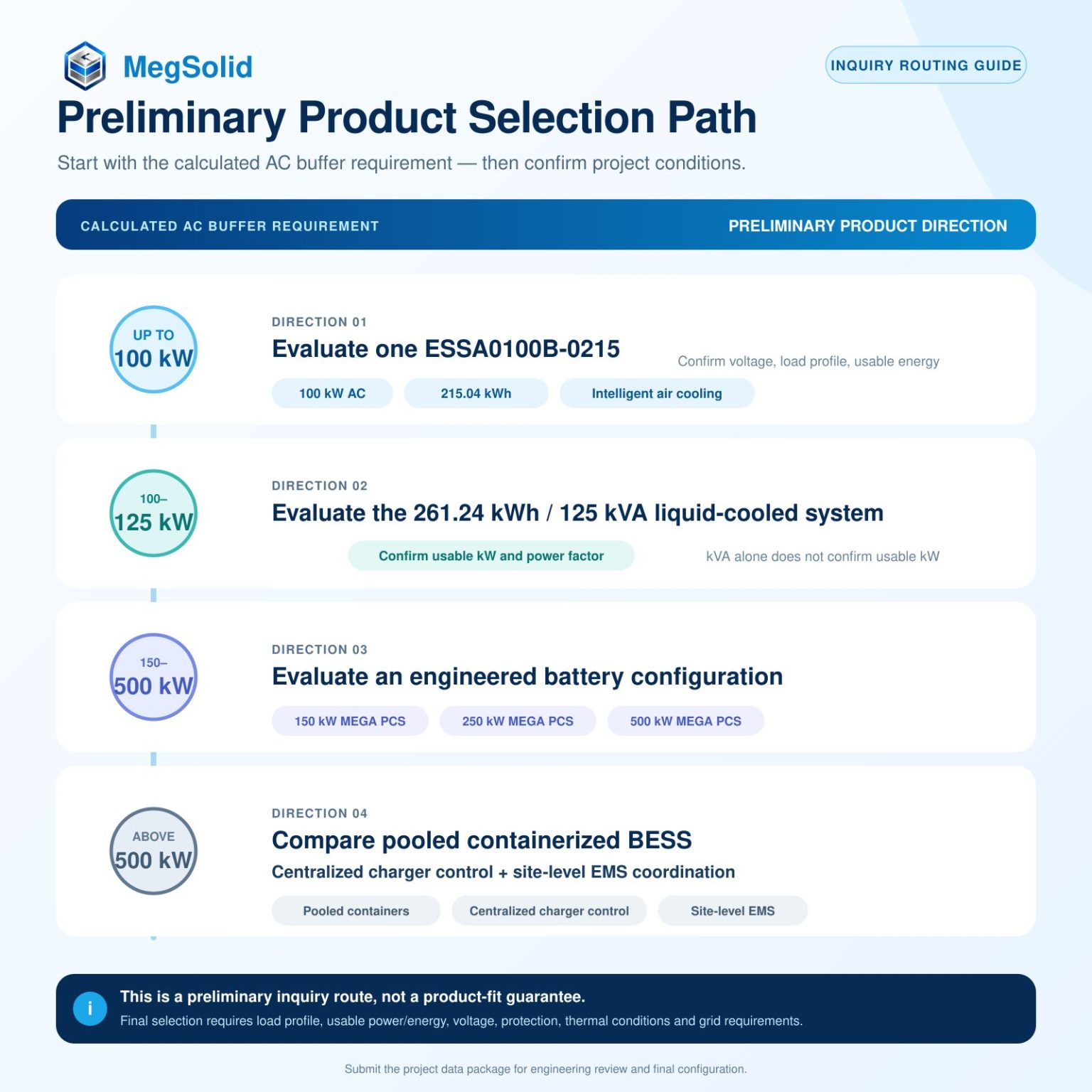
| Up to 100kW | Evaluate one ESSA0100B-0215 |
| 100–125kW | Evaluate the 261.24kWh/125kVA liquid-cooled system; confirm usable kW and power factor |
| 150–500kW | Evaluate an engineered battery configuration with 150kW, 250kW or 500kW MEGA PCS |
| Above 500kW | Compare pooled containerized BESS and centralized charger control |
This table is a preliminary inquiry route, not a product-fit guarantee. Final selection still depends on usable power, energy duration, charger profile, voltage, protection, thermal conditions, grid requirements and the validated system architecture.
For deeper model-level context, review the 215kWh outdoor cabinet ESS engineering guide.
AC-Coupled, DC-Coupled and Pooled BESS Architectures
| Architecture | Main advantage | Main procurement risk |
|---|---|---|
| AC-coupled BESS | Clear equipment boundaries; practical for retrofits | PCS, switchboard, meter and charger controls must coordinate |
| DC-coupled storage | Potentially more integrated power path | DC compatibility, insulation, fault isolation and certification responsibility |
| Central pooled BESS | Shares grid capacity and stored energy across ports | Common controls and common-point failure modes |
| Battery per port | Isolates each charger’s capacity | More stranded energy and duplicated equipment |
The DOE reference tables distinguish pooled and separate systems and show why pooling can use grid capacity more efficiently. Select the architecture from the complete loss map, fault study and responsibility matrix—not an efficiency headline.
For sites expected to expand from hundreds of kilowatts into megawatt-scale fleet charging, compare modular cabinets vs. containerized ESS before fixing the civil layout.
EMS and Charger Communication Must Enforce the Grid Limit
The site controller must keep PCC demand within the approved limit while protecting battery SOC and allocating available power among chargers.
A practical hierarchy is:
- PCC meter: Measures real import/export power.
- Site EMS: Calculates the allowed charger and BESS setpoints.
- PCS/BMS: Enforces battery voltage, current, SOC and temperature limits.
- Charging station management system: Allocates charging power among ports and sessions.
- Charger: Delivers the vehicle-requested power within the assigned limit.
The Open Charge Alliance defines OCPP as the protocol between charging stations and charging-management systems. Its supported versions include 1.6, 2.0.1 and 2.1. Review the official OCPP version information, but do not treat a protocol label as proof of tested interoperability.
Freeze all required signals in a communication matrix. The Architecture de communication entre le BMS et l'EMS should define ownership of SOC limits, power commands, alarms, emergency stops and fail-safe behavior.
Safety and Compliance Are System-Level Responsibilities
The charger, stationary battery, PCS and complete ESS have different approval boundaries. UL Solutions’ EV and EVSE standards map distinguishes these equipment categories. The project country and authority determine the applicable standards.
The EPC should confirm:
- Electrical: Transformer loading, short-circuit level, grounding, protection and disconnects.
- Matériel : Model-specific charger, battery, PCS and complete-ESS documents.
- Site : Fire spacing, drainage, impact protection, ventilation, temperature, dust and corrosion.
- Grid interaction: Import limiting, export control, harmonics and loss-of-grid behavior.
Do not generalize a certificate from the charger to the BESS, from a cell to the cabinet, or from one MegSolid model to another. Before issuing the purchase order, use the framework for how to qualify a commercial battery energy storage supplier and request the actual document scope.
EV Charging BESS RFQ Checklist
Send the following project data before requesting a firm system recommendation:
- Project country, site address and installation environment.
- Charger manufacturer, model, port quantity and rated kW per port.
- Transformer data, current peak demand and approved import/export limits.
- Single-line diagram and proposed BESS connection point.
- Site-load data, expected sessions, session kWh and dwell time.
- First-hour, design-day and future expansion profiles.
- PV, generator, backup-mode and reserve-SOC requirements.
- Applicable standards, delivery date, commissioning and warranty scope.
FAQ
Q1 : Un système de stockage d'énergie par batterie (BESS) permet-il toujours d'éviter la mise à niveau du transformateur d'une borne de recharge pour véhicules électriques ?
Non. Un système de stockage d'énergie par batterie (BESS) peut réduire la capacité requise du réseau lorsque les pics de charge sont intermittents et que la batterie a le temps de se recharger. Il ne peut toutefois pas pallier le sous-dimensionnement d'un transformateur si la demande quotidienne de charge dépasse de manière soutenue l'énergie que le raccordement au réseau est en mesure de fournir.
Q2 : La capacité d'un système de stockage d'énergie (BESS) destiné à la recharge des véhicules électriques doit-elle être exprimée en kW ou en kWh ?
Les deux. La puissance (PCS en kW) détermine l'ampleur du déficit instantané du réseau que le système de stockage par batterie (BESS) peut couvrir. La capacité en kWh de la batterie détermine la durée pendant laquelle elle peut couvrir ce déficit et le nombre de sessions qu'elle peut prendre en charge avant d'être rechargée.
Q3 : Un armoire de 100 kW/215,04 kWh peut-elle prendre en charge un chargeur rapide en courant continu de 150 kW ?
Cela dépend de la puissance disponible sur le réseau et des autres charges de l'installation. Si au moins 50 kW restent disponibles sur le réseau au niveau de la limite étudiée, le déficit de puissance du système de stockage d'énergie par batterie (BESS) peut être de 100 kW ou moins. Les calculs relatifs à l'énergie et à la recharge doivent toutefois être valides. La puissance nominale d'un chargeur de 150 kW ne suffit pas à elle seule à déterminer la réponse.
Q4 : Quelle capacité de stockage de batterie est nécessaire pour quatre bornes de recharge de 150 kW ?
Il n'existe pas de valeur universelle en kWh. Le test de la première heure du DOE part d'une valeur de 150 kWh par borne et soustrait l'énergie fournie par le réseau pendant cette heure. La conception finale doit également prendre en compte l'utilisation prévue lors d'une journée type, les pertes de conversion, le niveau de charge utile (SOC), la dégradation et la recharge entre deux sessions.
Q5 : La borne de recharge peut-elle continuer à fonctionner en cas de coupure de courant ?
À condition que le système de contrôle et de surveillance (PCS), l'appareillage de commutation, les dispositifs de protection, les commandes et les chargeurs soient conçus et mis en service pour un fonctionnement hors réseau. L'installation d'une batterie à elle seule ne suffit pas à assurer une capacité de recharge en cas de coupure de courant. Le nombre de sessions prises en charge sera limité par l'énergie utilisable réservée.
Q6: Is AC coupling or DC coupling better for battery-buffered charging?
AC coupling often provides clearer equipment boundaries and can simplify retrofits. DC coupling may offer a more integrated power path but requires tighter DC compatibility, fault protection and charger-vendor coordination. The project architecture and certification scope should decide the choice.
Q7: Can on-site solar reduce the required BESS size?
Solar can support daytime charging and replenish the battery, but variable PV output should not be counted as firm capacity for an evening or low-irradiance design event. Run separate conservative and expected-production cases.
Q8: How quickly must the BESS recharge between EV sessions?
The recharge window depends on arrival patterns, grid headroom, SOC reserve and the next expected peak. An EMS should restore sufficient SOC without exceeding the transformer or utility import limit.
Q9: Does OCPP automatically integrate the charger with the BESS EMS?
No. OCPP supports communication between charging stations and their management system. The project still needs a tested interface between the charger controller, site EMS, PCC meter, PCS and BMS, including timeout and fail-safe behavior.
Q10: What information does a BESS supplier need to quote an EV charging project?
At minimum: charger quantity and power, transformer and PCC limits, site load profile, session forecast, grid voltage, PV or generator data, required backup mode, installation environment, applicable standards and commissioning scope.
Q11: What is a BESS for an EV charging station?
Un système BESS destiné à une borne de recharge pour véhicules électriques stocke de l'énergie lorsque le réseau dispose de capacité suffisante et la restitue lorsque la demande des chargeurs dépasse une limite définie pour le site. Il peut permettre d'écrêter les pics de consommation, d'assurer une recharge rapide malgré les contraintes du réseau et de maintenir un fonctionnement limité en cas de coupure de courant, à condition que l'ensemble du système soit conçu pour ces fonctions.
Q12: How do EPCs size battery storage for DC fast charging?
EPCs calculate the maximum AC power deficit at the point of connection, then integrate that deficit over the first-hour and design-day charging profiles. The nominal battery is adjusted for conversion losses, usable SOC, end-of-life SOH, temperature and recharge requirements.
Q13: Is a 100kW/215kWh BESS suitable for EV fast charging?
It can be suitable when the required battery contribution is no more than the validated PCS power and the usable energy can cover the charging event with adequate reserve. Charger rating, transformer headroom, site load and session frequency must be evaluated together.