
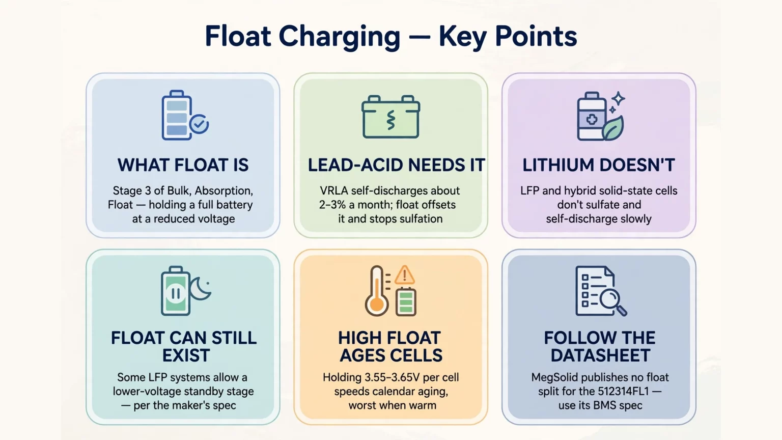
To answer what is float charging, it is the third stage of a traditional 3-stage charge profile (Bulk, Absorption, Float) that holds a battery at a reduced float voltage after main charging completes.
Continuous float charging a battery is required for VRLA and AGM lead-acid banks to compensate for self-discharge and prevent irreversible lead sulfate crystallization on the electrodes.
By contrast, lithium iron phosphate (LFP) and hybrid solid-state batteries do not require lead-acid-style continuous maintenance charging, though certain LFP systems permit a reduced-voltage float or standby stage after absorption.
Commissioning problems arise when technicians apply unverified lead-acid float and equalization profiles to lithium banks, or hold cells continuously at inappropriate high voltages that accelerate calendar aging.
When planning a Lithium Battery for 5G Base Station: Replace Lead-Acid retrofit or evaluating how to Choose a 30 kW, 40 kW, or 50 kW Three-Phase Hybrid, charging parameters must follow verified battery and inverter specifications:
- MEG-Solid-512314FL1: 51.2V / 314 Ah (16.07 kWh) hybrid solid-state LFP battery (43.2V to 57.6V working range, 57.6V charging voltage, 200A max charge / 200A max continuous discharge, 8,000 cycles at 80% DoD, RS485/RS232/CAN)
- G2S-C Single-Phase Inverter Series (R3KL1DA-G2S-C to R6KL1DA-G2S-C): 3 kW to 6 kW AC-coupled storage inverters with a 48V rated battery input (40V to 58V range), 60A to 120A model-specific maximum battery current, CAN BMS communication, and support for lithium-ion and lead-acid battery categories (subject to BMS protocol verification)
- R30KH3 / R40KH3 / R50KH3 Three-Phase Hybrid Inverters: 30 kW, 40 kW, and 50 kW C&I hybrid inverters supporting a 150V to 800V DC battery range (33 kW, 44 kW, and 55 kW max battery charge/discharge power) and under 10 ms backup switching
What Is Float Charging & What Is Float Voltage? Lead-Acid Maintenance vs. Lithium Standby Stages
Understanding what is float voltage starts with comparing how lead-acid and lithium cells behave once they approach full State of Charge (SoC).
Float voltage is the reduced DC voltage setpoint maintained after Constant Current (Bulk) and Constant Voltage (Absorption) charging phases finish.
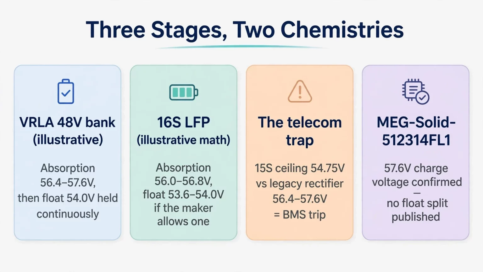
In an illustrative 48V (24-cell) VRLA lead-acid reference bank at 25°C, absorption occurs around 56.4V to 57.6V (2.35V to 2.40V per cell), subject to the manufacturer's datasheet and temperature compensation.
The charger then drops to a continuous battery charger float charge around 54.0V (2.25V per cell) during standby operation: Float voltage for 24 series-connected VRLA cells = 24 × 2.25V per cell = 54.0V.
Why Lead-Acid Requires Continuous Float Current
Standby VRLA and AGM lead-acid batteries experience ongoing self-discharge (around 2% to 3% per month at 25°C for many VRLA blocks, and rising substantially at elevated ambient temperatures).
Left without maintenance charging, discharging lead-acid plates convert active material into hard, insulating lead sulfate (PbSO4) crystals that permanently reduce capacity.
Maintaining a continuous float voltage according to the lead-acid manufacturer's specification compensates for self-discharge and prevents plate sulfation.
How Lithium Charging Differs from Lead-Acid Float Maintenance
Lithium iron phosphate and hybrid solid-state cells do not experience lead sulfate crystallization and exhibit low self-discharge.
On the official datasheet for the MEG-Solid-512314FL1 : batterie de stockage d'énergie à électrolyte solide de 51,2 V et 314 Ah, self-discharge is specified at no more than 2% per month (at 25°C and 50% SoC).
Rather than relying on lead-acid trickle maintenance, lithium systems primarily use Constant Current / Constant Voltage (CC/CV) charging governed by BMS limits.
Depending on the manufacturer's charging architecture, the system either terminates charging once current tapers or transitions to a reduced-voltage float/standby stage.
For example, Victron Energy's official LFP battery documentation specifies a 56.8V absorption stage followed by a reduced 54.0V float stage on 51.2V systems, proving that LFP systems do not universally forbid a lower-voltage float stage.
However, those parameters belong to Victron's specific battery design and cannot be assumed as factory defaults for MegSolid or other manufacturers without checking the respective model specification.
Electrochemical Risks of Applying Improper Float Settings to Lithium BESS
Applying an unverified lead-acid battery charger float charge or holding lithium cells continuously at excessive voltage introduces three distinct engineering risks.
1. Accelerated High-SoC and High-Voltage Calendar Aging
The primary degradation mechanism when holding LFP cells continuously at elevated voltage is accelerated calendar aging rather than immediate metallic plating.
Electrochemical side reactions at the electrode-electrolyte interface follow Tafel overpotential and Arrhenius temperature kinetics.
Holding an LFP pack continuously at high SoC and elevated terminal voltage (such as 3.55V to 3.65V per cell, or 56.8V to 58.4V on a 16S pack, especially at warm ambient temperatures) accelerates Solid Electrolyte Interphase (SEI) growth and electrolyte oxidation compared to resting at a lower voltage plateau.
2. Overcharge Stress and Condition-Dependent Lithium Plating Risks
Anodic lithium plating does not automatically occur during every float stage; instead, it depends on local anode potential, cell temperature, charging current magnitude, and SoC.
When the graphite anode is already near saturation (LiC6), forcing excessive current into the cell (particularly at low temperatures or under over-voltage conditions) can drive the anode potential toward 0.0V versus Li/Li+.
Under those abusive conditions, lithium ions can deposit as metallic lithium on the anode surface, consuming cyclable lithium inventory and degrading cell safety margins.
3. Nuisance BMS Over-Voltage Protection (OVP) Trips in Telecom Retrofits
Telecom base stations operate on nominal -48V DC rectifiers originally configured for 24-cell VRLA strings.
In many telecom retrofits, replacement lithium modules use a 15-series (15S, 48.0V nominal) LFP configuration to align with legacy -48V plant windows.
Using a typical cell upper limit of 3.65V per cell as an illustrative calculation, a 15S pack reaches 15 × 3.65V = 54.75V, while exact BMS protection thresholds vary by manufacturer and BMS model.
If a technician leaves a legacy rectifier in lead-acid absorption or equalize mode (56.4V to 57.6V), the bus voltage exceeds the illustrative 15S charging ceiling, which can trigger BMS Over-Voltage Protection (OVP) and disconnect the battery from the DC bus.
How Hybrid Inverters Use Float Voltage Settings in Lithium Systems
Installers configuring solar hybrid inverters or MPPT charge controllers ask how the float voltage parameter functions when operating with LFP batteries.
Across different inverter brands and charger topologies, float control logic varies: some systems terminate charging completely under BMS control, while manual voltage-mode profiles step the DC regulation target down to a lower float voltage after absorption finishes.
Illustrative Per-Cell Voltage Math vs. Real-World Current Flow
In general industry discussions of 16S (51.2V nominal) LFP banks, engineers examine illustrative per-cell voltage targets:
- Illustrative Absorption Calculation: 16 × (3.50V to 3.55V) = 56.0V to 56.8V.
- Illustrative Reduced Float Calculation: 16 × (3.35V to 3.375V) = 53.6V to 54.0V.
In an idealized steady-state circuit model where DC bus voltage exactly equals pack open-circuit voltage, theoretical current would approach zero. Equal voltage values alone do not establish that actual battery current is zero.
Setting a lower float voltage may reduce prolonged high-voltage exposure after absorption charging.
However, actual battery current depends on pack voltage, SoC, connected loads, BMS controls, and inverter topology, so a fixed float setpoint cannot guarantee zero battery current or 100% solar load coverage in real-world operation.
In practice, LFP open-circuit voltage varies with State of Charge, cell temperature, relaxation time, and charge-discharge hysteresis.
Risks of Misconfiguring Manual Float Setpoints
When an inverter operates in manual open-loop voltage mode without BMS coordination, improper float voltage entries cause operational issues:
- Float Set Excessively High: Holding the pack continuously near its upper charging cut-off all afternoon increases high-voltage calendar aging stress.
- Float Set Below Resting Pack Voltage: Setting float to nominal voltage (such as 51.2V on a 16S pack, which cannot be mapped to a single fixed SoC) can allow the battery to discharge into daytime loads before the solar charger resumes regulation, depending on charger mode, PV generation, load demand, and actual pack OCV.
Illustrative Voltage Calculations & Verified MegSolid Hardware Parameters
When commissioning storage systems, engineers must strictly separate illustrative per-cell math (or third-party LFP examples) from verified MegSolid factory parameters.
For the MEG-Solid-512314FL1, MegSolid's official documentation confirms a working voltage range of 43.2V to 57.6V and a standard charging voltage / upper cut-off of 57.6V (with a 43.2V discharge cut-off), without publishing a separate manual absorption/float split such as 56.0V to 56.8V or 53.6V to 54.0V.
Field settings must always follow the specific battery model's charging specification and approved BMS protocol requirements. Compare the Systèmes de stockage d'énergie à usage résidentiel, Systèmes de stockage d'énergie C&I, et Energy Storage Inverter & PCS categories before changing site commissioning defaults.
| Configuration / Hardware Model | Series Cell Count | Nominal Voltage (Vnom) | Verified MegSolid Datasheet Window / Spec | Illustrative Absorption Math (3.50–3.55V/cell) | Illustrative Standby / Float Math (3.35–3.375V/cell) | Control & Commissioning Basis |
|---|---|---|---|---|---|---|
| VRLA / AGM Lead-Acid (Industry Reference) | 24S Lead (2.0V) | 48,0 V | Not applicable (third-party lead-acid) | 56.4V to 57.6V (2.35–2.40V/cell) | 54.0V (2.25V/cell continuous float) | Follow lead-acid OEM manual |
| Generic 15S LFP Rack (Illustrative Math) | 15S LFP (3.2V) | 48,0 V | Illustrative industry 15S calculation | 52.5V to 53.25V (illustrative) | 50.25V at 3.35V/cell (illustrative) | Verify specific 15S pack datasheet & BMS |
| Generic 16S LFP Rack (Illustrative Math) | 16S LFP (3.2V) | 51,2 V | Illustrative industry 16S calculation | 56.0V to 56.8V (e.g., 56.8V in Victron LFP guide) | 53.6V to 54.0V (e.g., 54.0V in Victron LFP guide) | Verify specific 16S pack datasheet & BMS |
| MEG-Solid-512314FL1 (314Ah / 16.07kWh) | 16S Hybrid Solid-State LFP | 51,2 V | Working range: 43.2V–57.6V; Charging voltage: 57.6V; Cut-off: 57.6V / 43.2V | Not published as a separate MegSolid spec (57.6V confirmed charge voltage) | Not published as a separate MegSolid spec | Follow MegSolid charging spec & RS485/RS232/CAN BMS limits |
| G2S-C Single-Phase Inverter (3–6 kW) | Low-voltage battery input | 48V Rated Input | 40V–58V DC range; 60A–120A max current (by model); CAN BMS port | Governed by approved BMS or battery OEM spec | Governed by approved BMS or battery OEM spec | CAN closed-loop BMS (verify protocol) or verified battery spec |
| R30KH3 / R40KH3 / R50KH3 HV Hybrid (30–50 kW) | High-voltage HV cluster | 150V to 800V DC | 150V–800V DC battery range; 33/44/55 kW max charge/discharge | Governed by connected HV battery spec & BMS | Governed by connected HV battery spec & BMS | Follow inverter and HV battery BMS specifications |
Closed-Loop BMS Communication & Current Limiting on MegSolid G2S-C and R30KH3–R50KH3 Inverters
When a compatible battery BMS and inverter support closed-loop communication, the BMS can provide charge voltage and current limits according to battery operating conditions.
The actual charge termination, standby, and recharge behavior depends on the approved BMS protocol and control strategy.
Before pairing any battery and inverter, installers must verify both physical port compatibility and protocol matching between the specific models.
Single-Phase 48V Architecture: G2S-C Series (3 kW to 6 kW) and Current Limiting Math
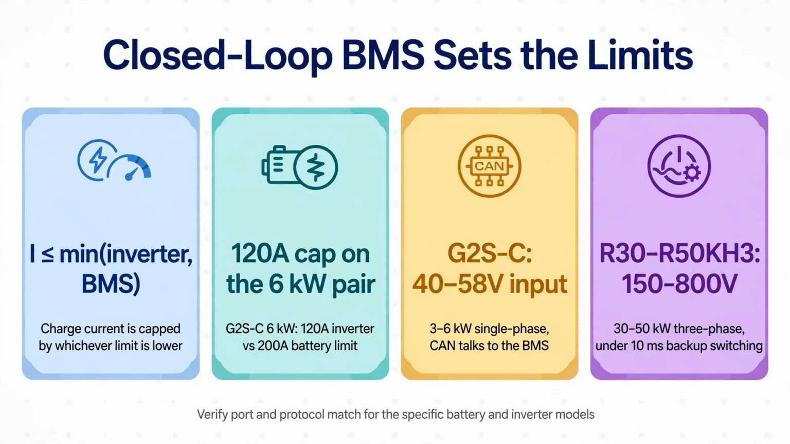
Designed for residential and light commercial AC coupling, the MegSolid G2S-C Single-Phase Energy Storage Inverter (R3KL1DA-G2S-C through R6KL1DA-G2S-C) operates across a 40V to 58V DC battery input window.
Official G2S-C documentation specifies CAN for battery BMS communication, support for lithium-ion and lead-acid battery categories (alongside hybrid solid-state compatibility noted in MegSolid documentation, all subject to BMS protocol verification for specific models), and model-dependent maximum battery charge/discharge currents of 60A, 72A, 80A, 92A, 100A, and 120A across the 3 kW to 6 kW lineup.
Meanwhile, the MEG-Solid-512314FL1 battery (51.2V / 314 Ah / 16.07 kWh, internal impedance no more than 15 milliohms) specifies a 200A maximum charging current and a 200A maximum continuous discharge current.
In any paired system, maximum charging current is constrained by the lower of the inverter rating and the BMS limit: Icharge ≤ min(Iinverter, IBMS).
For the flagship 6 kW R6KL1DA-G2S-C model rated at 120A maximum battery current: maximum charging current ≤ min(120A, 200A) = 120A.
When paired with a compatible MEG-Solid-512314FL1 battery, the G2S-C inverter must respect both the battery BMS limits and its own model-specific maximum battery current.
The 6 kW G2S-C model is rated for up to 120A charge and discharge current, below the battery pack's published 200A maximum charging current, and actual operating current is further governed by inverter AC/DC power limits, real-time battery voltage, and cell temperature thresholds.
Three-Phase High-Voltage C&I Control: R30KH3, R40KH3, and R50KH3 (30 kW to 50 kW)
For commercial solar-plus-storage plants, the MegSolid Three-Phase Hybrid Inverter series (R30KH3, R40KH3, and R50KH3) supports high-voltage hybrid solid-state and lithium-ion battery strings from 150V to 800V DC, subject to verifying BMS protocol compatibility for the selected high-voltage battery cluster.
The R30KH3 (30 kW), R40KH3 (40 kW), and R50KH3 (50 kW) provide maximum battery charge/discharge power ratings of 33 kW, 44 kW, and 55 kW, with maximum PV input power of 45 kW, 60 kW, and 75 kW respectively.
The R50KH3 series supports 4-channel MPPT tracking, 100% unbalanced three-phase load output, and under 10 ms backup switching inside an IP65 enclosure.
How Closed-Loop BMS Control Coordinates Charging and Standby
Rather than relying on a single static open-loop voltage, closed-loop communication between an approved BMS and inverter coordinates charging dynamically:
- Dynamic Voltage and Current Limits: The BMS transmits permissible charge voltage and current limits based on real-time cell voltages and temperatures.
- Top-of-Charge Balancing Coordination: As cells approach full charge, the BMS can request reduced charging current according to its internal balancing and protection logic.
- Protocol-Dependent Standby and Recharge: Charge termination, standby voltage regulation, and recharge triggers (whether based on SoC thresholds, cell voltage, or coulomb counting) are executed according to the specific BMS firmware and inverter control strategy.
The MEG-Solid-512314FL1 hybrid solid-state LFP battery is rated for 8,000 cycles at 80% depth of discharge (DoD), with internal impedance no more than 15 milliohms. It specifies 200A maximum charging current and 200A maximum continuous discharge current, with charging from 0°C to 45°C and discharging from -20°C to 60°C.
In a compatible closed-loop configuration, the battery BMS supplies dynamic voltage and current limits based on cell conditions. Exact charge termination, standby behavior, and recharge thresholds depend on the approved BMS protocol and charger control strategy rather than a single universal setting.
FAQ
What is float charging on a battery charger?
Float charging is a post-absorption stage where a charger maintains a battery at a reduced DC voltage. In standby VRLA and AGM lead-acid systems, continuous float charging is required per manufacturer specifications to compensate for self-discharge and prevent irreversible plate sulfation.
Must all lithium iron phosphate (LFP) batteries completely eliminate the float stage?
No. While lithium batteries do not need lead-acid-style continuous trickle maintenance, some LFP systems permit a lower-voltage float stage after absorption. A manufacturer-specific 51.2V LFP example uses 56.8V absorption and 54.0V float. Never apply these settings to another battery without its approved documentation.
Does setting a 53.6V float voltage on a 16S LFP pack guarantee 0 A battery current?
No. Even if an idealized circuit shows the DC bus voltage equal to pack open-circuit voltage, equal voltage values do not guarantee zero real-world battery current. Current depends on pack voltage, SoC, connected loads, BMS controls, and inverter topology.
What happens if manual float voltage is set to 51.2V on a 16S LFP system?
Because 51.2V is nominal voltage and the LFP voltage-to-SoC curve is relatively flat, 51.2V cannot be mapped to one fixed SoC percentage. Whether the battery discharges during daylight depends on charger logic, available PV power, connected loads, and actual pack open-circuit voltage.
What charging voltage is confirmed on the MEG-Solid-512314FL1 datasheet?
The published MEG-Solid-512314FL1 specification confirms a 43.2V to 57.6V working range, a standard charging voltage of 57.6V, and 57.6V charge/43.2V discharge cutoff values. No separate manual absorption/float voltage split is published for this model.
Why can 15S lithium batteries trip offline on legacy -48V telecom rectifiers?
Legacy lead-acid rectifiers may output 56.4V to 57.6V during absorption or equalization. For an illustrative 15S LFP design, 15 × 3.65V = 54.75V. An unadjusted rectifier can exceed the lithium pack’s approved voltage limit and trigger BMS over-voltage protection.
What is the primary degradation risk of holding LFP batteries at high float voltage?
Holding LFP cells continuously at elevated SoC and voltage (for example, 3.55V to 3.65V per cell) primarily accelerates calendar aging through SEI growth and electrolyte oxidation, especially in warm conditions. Metallic lithium plating is a separate condition-dependent risk involving temperature, current, and overcharge severity.
How is charging current limited when pairing G2S-C with MEG-Solid-512314FL1?
The charging current cannot exceed the lower approved limit of the inverter and the battery BMS, subject also to operating power and temperature. Although the battery is specified at up to 200A, the 6 kW G2S-C model is rated for 120A maximum battery current, limiting that pairing to 120A or less.
Which BMS communication port is confirmed on the MegSolid G2S-C inverter?
The G2S-C single-phase inverter specifies CAN battery BMS communication and a 40V to 58V DC input window. MEG-Solid-512314FL1 lists RS485, RS232, and CAN; installers should use the appropriate CAN interface and verify actual protocol and register compatibility before commissioning.
What voltage range do R30KH3, R40KH3, and R50KH3 hybrid inverters support?
The R30KH3, R40KH3, and R50KH3 support a 150V to 800V DC battery input window with 33 kW, 44 kW, and 55 kW maximum battery charge/discharge power respectively. Verify the connected high-voltage battery BMS protocol and approved charging limits before operation.
Conclusion: Match Float and Standby Settings to Verified BESS Specifications
Understanding what is float charging helps engineers distinguish between mandatory lead-acid maintenance charging and lithium standby regulation.
Avoiding unverified lead-acid voltage profiles, respecting inverter-to-battery current limits, and using verified closed-loop BMS communication protect both calendar life and backup reliability.
For telecom DC plant retrofits, review the Lithium Battery for 5G Base Station lead-acid replacement guide. For commercial solar-plus-storage sizing, review the 30 kW, 40 kW, or 50 kW Three-Phase Hybrid inverter engineering guide.
Browse MegSolid Hybrid Solid-State Energy Storage Systems for available system architectures. Share your battery model, inverter model, charging settings, CAN/RS485 interface details and operating conditions to request factory-verified commissioning documentation.