 Yiya kumxholo
A BESS CT polarity PASS releases the named PCC signal for the operating modes covered by the test. Usable kWh, power quality and availability stay under their own procedures. Before the metering result can pass, the electrical and controls teams have to agree on the measurement point, CT ratio, polarity, phase pairing, software sign and timestamp.
When a 400 V MegSolid ESSA0100B-0215 follows a charge or discharge command, a site-installed PCC measurement chain with reversed CTs can still report the opposite direction. The cabinet response and the site measurement have separate test boundaries. The C&I BESS testing sequence places the final CT, voltage-input, meter and network checks at site.
Peak shaving and zero export both act on the PCC signal. The Inkcazelo yomgangatho wokulawula we-BESS wokungathumeli ngaphandle sets the control boundary. Commissioning has to show that the installed signal moves in the same direction as the physical power flow.

Why CT Polarity Alone Cannot Prove PCC Power Direction
A conventional CT converts primary current into a smaller secondary current. Import, export, charge and discharge acquire their meaning later in the measurement path. CT orientation, secondary terminals, voltage-phase pairing, meter settings, communications registers and the EMS sign all affect the final value.
A polarity test can pass while the live PCC value remains wrong. P1/P2 and S1/S2 may agree, but L1 current may be paired with L2 voltage. The meter may calculate the correct primary current and the EMS may scale it again. Even a correct value becomes misleading when its timestamp is compared with the wrong PCS command.
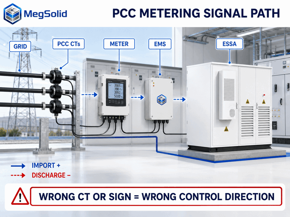
Commissioning follows the signal from the primary conductor to the control response. The signed result covers the meter, settings and operating mode used during that run.
A Plausible Reading Can Still Drive the Battery the Wrong Way
Take a factory importing about 420 kW at its main incomer. The commissioning engineer commands 20 kW discharge. The PCS reaches its setpoint, yet the PCC meter rises towards 440 kW. Viewed on separate screens, neither number looks absurd.
The engineer holds the command at that point. Reversed CTs are one explanation; a voltage/current phase mismatch, duplicated CT multiplier or inverted EMS sign can produce a similar trend. A clock offset may also place a load increase beside the wrong battery command.
The original per-phase values are saved before anyone changes wiring or software. Troubleshooting then moves from the conductors towards the EMS tag, one layer at a time.
Start With the Boundary and Sign Convention
A correctly wired meter at the wrong point cannot run whole-site peak shaving. For factory peak shaving, the PCC measurement normally sits upstream of the site loads and BESS feeder so it sees total grid exchange. A meter on the BESS feeder sees cabinet power only. A meter on one production board misses every load outside that board.
Trace the approved single-line diagram and mark:
- the primary conductor passing through each CT;
- the voltage take-off used by the meter;
- the meter or gateway publishing active power;
- the EMS tag receiving that value;
- every multiplier or sign conversion between the meter and controller.
I- 400 V BESS switchboard guide separates the cabinet feeder from the incomer, bus and site protection. The drawing used for commissioning should show that physical distinction.
Write the sign convention beside the drawing. With grid import positive and BESS charging positive:
PIkomiti yezobutyebi yelizwe ≈ Psite load + PBESS
Discharge makes PBESS negative, so PCC import falls when the facility load stays roughly steady. Charging makes import rise. Projects may adopt a different sign convention. The meter, EMS, PCS, SCADA and signed test still need to agree on one definition.
What to Verify at the CT and Meter
The de-energized review starts at the installed CT. The nameplate gives its primary and secondary rating, accuracy class, rated burden and terminal markings; some models also carry an individual serial number. The meter input must match the installed 1 A or 5 A secondary circuit.
Ratio and Scaling
A 600/5 A CT has a ratio of 120:1. If a suitable test instrument measures 2.5 A secondary, the corresponding primary current is 300 A.
Primary current = secondary current × CT ratio
A meter configured for 600/1 A on that 600/5 A circuit produces a fixed-factor error. A similar error appears when the meter already publishes primary amperes and the EMS multiplies the register again.
Put the nameplate ratio beside the meter setting, protocol unit and EMS multiplier. The burden calculation also includes secondary cables, terminals, test blocks and any instruments connected in series. Long secondary runs deserve attention because excess burden adds ratio and phase error.
Polarity and Terminal Markings
CTs may use P1/P2 and S1/S2, H1/H2 and X1/X2, K/L and k/l, or an arrow. Follow the installed manufacturer's diagram and the approved project drawing. Cable colours do not prove polarity.
Do not leave an energized conventional CT secondary open. Schneider Electric's meter documentation also requires CT secondary grounding in accordance with the equipment instructions and warns against using a meter display to prove that a circuit is de-energized. Qualified electrical personnel must use the approved isolation, shorting and test arrangements. The manufacturer safety manual controls the work method.
Phase Association
Each current channel needs the voltage from the same phase. Current from L1 paired with L2 voltage can show a believable current magnitude while active power, reactive power and power factor become wrong. When one phase contributes negative power, the three-phase total may still look plausible.
Check voltage, current, active power, reactive power, power factor and phase angle per phase. A phasor display helps locate swapped phases and reversed current direction. Schweitzer Engineering Laboratories lists phasor display as a commissioning tool for verifying CT polarity and phasing in its SEL-787 documentation. The project meter or power-quality analyzer can provide the same comparison when it supports a phasor view.
Pair Secondary Injection With a Live Direction Test
Secondary injection checks the downstream circuit without relying on facility load. Known current and voltage quantities confirm meter input scaling, phase assignment, active-power sign, register mapping and the value received by the EMS.
Secondary injection leaves the primary conductor direction untested. Placing the leads close to the meter may also bypass field terminals and cable runs. Mark the injection point and the portion of the circuit covered by the test.
An end-to-end live test closes the remaining gap:
- 1. Establish a stable facility load or controlled primary-current condition.
- 2. Compare each phase with a calibrated reference instrument.
- 3. Record the baseline PCC power and meter quality state.
- 4. Issue a small BESS charge command and return to zero.
- 5. Issue a small discharge command of similar magnitude.
- 6. Compare command, PCS power and PCC movement on one time base.
- 7. Interrupt the selected meter signal and observe the timeout, alarm, fallback and recovery.

The first command only has to stand clear of normal load movement and meter resolution. On one site that may be 10 kW; on another, 20 kW still disappears inside production swings. The procedure sets a workable value from the actual load profile, available battery power and test conditions.
For MegSolid systems connected to third-party switchgear and meters, the interface review can align CT direction, protocol scaling and the approved fallback before automatic control is released.
Put Every Test Trend on One Time Base
A PCC meter may publish an averaged result after the PCS has reacted. When the EMS, meter and SCADA clocks differ, the exported trend can pair a command with the wrong response. That can send the team back to wiring that was correct all along.
Before the live step, compare the displayed time on the meter, PCS, EMS and historian. Record the time source and synchronization status for every device. NTP, SNTP, PTP, GPS and local site clocks appear in industrial systems; the required method depends on equipment capability and test resolution.
Clock tolerance depends on the control response, meter update rate and evidence resolution. The procedure states the permitted difference, sampling interval, averaging window and time zone. A known event should appear at the expected time in every record. If analysis applies a time correction, the report keeps both the original timestamp and the adjustment.
I- Uluhlu lweendawo ze-BESS SCADA should use the same tag names, units and quality fields as the commissioning trace. The Isakhiwo sonxibelelwano se-BMS ne-EMS explains which limits remain local when the PCC signal becomes stale or disappears.
Diagnose the Pattern Before Changing the Wiring
Capture per-phase values before moving wires or changing software. The pattern usually narrows the fault faster than the total kW value.
| Result at site | Check first | Evidence needed after correction |
|---|---|---|
| All three phase powers are negative during known grid import | CT orientation or overall meter sign | Physical orientation record and positive import on the agreed convention |
| One phase is negative while two are positive | One reversed CT or wrong voltage/current pairing | Corrected per-phase phasor and power record |
| Current and kW differ by a steady factor | CT primary/secondary setting, 1 A/5 A input or duplicate multiplier | Nameplate, settings and reference-current comparison |
| Total kW is near zero under a substantial balanced load | Phase contributions cancelling | Per-phase sign and phase-angle check |
| Power factor looks implausible while current is normal | Voltage phase mapped to the wrong current channel | Confirmed voltage/current pairing |
| PCS responds but the PCC changes later or barely moves | Wrong boundary, moving site load or timestamp mismatch | Synchronized controlled step with meter location shown |
| Peak-shaving power hunts around the target | Signal delay, duplicated filtering, sign error or unsuitable deadband | Raw update timing and stable closed-loop trend |
| Meter display and EMS value disagree | Register, byte order, unit or scaling map | Side-by-side display, register and EMS comparison |
Negative active power may mean real export, reversed CT polarity or an inverted software convention. After each change, repeat the same controlled step and keep the failed trace beside the corrected one.
Where the ESSA Cabinet Ends and Site Metering Begins
In the 420 kW factory example, the ESSA0100B-0215 connects to an existing 400 V main board for peak shaving. Its published 100 kW rated AC power and 215.04 kWh nominal energy describe the cabinet. PCC location, CT orientation and site-meter scaling remain part of the installed electrical system.
Per-phase inspection finds negative active power on all three incomer phases under known grid import. The nameplate ratios match the programmed values, which moves attention to physical orientation. The CT arrows oppose the direction shown on the approved drawing.
The electrical team corrects the CT orientation under the approved isolation procedure. Repeating the 20 kW discharge step now moves PCC import towards 400 kW, and a charge step moves it upward. The figures illustrate direction only. Site-load movement, losses, meter accuracy and sampling delay set the actual comparison band.
| Test state | Cabinet-side result | Expected PCC movement with stable load |
|---|---|---|
| Zero command | Active power inside the defined zero band | Baseline import |
| Controlled charge | Battery absorbs AC power | Import rises |
| Controlled discharge | Battery supplies AC power | Import falls |
| Meter data stale or missing | EMS follows the approved fallback | Alarm, data-quality state and recovery are recorded |
I- BESS site acceptance test procedure carries the corrected metering result into the wider site release. It should reference the same meter, CT set, settings file and trend.
Where the Metering PASS Ends
An end-to-end metering PASS covers the named measurement chain under the stated test method. Capacity acceptance has a separate SOC window, power setpoint, temperature basis, auxiliary treatment and AC measurement point. Power-quality testing uses its own analyzer placement and operating conditions. A later reliability run records alarms, curtailment and availability.
I- Uvavanyo lomthamo we-BESS yorhwebo covers the energy calculation. A later meter replacement, CT change or EMS remapping reopens the affected metering tests even when the battery hardware remains unchanged.
At handover, the operator needs three matching references: the identified PCC meter and CT set, the approved settings and software record, and the signed end-to-end metering test.
The cabinet-side signal and the released operating mode should match those three references.
Imibuzo Ebuzwa Rhoqo
1. What happens if BESS CT polarity is reversed?
Current magnitude may look normal while active power carries the opposite sign. A peak-shaving or zero-export controller can then drive the command the wrong way. Hold the run and trace the direction from the CT markings through to the EMS tag.
2. Can reversed CT polarity make grid import rise during BESS discharge?
Yes. The PCS can deliver the requested discharge while the PCC meter or EMS reports it with the opposite sign. Repeat a small charge and discharge step under a steady load and watch which way grid import moves.
3. How should CT polarity be checked safely?
Qualified electrical personnel must work to the CT and meter manuals, the site isolation procedure and local electrical rules. An energized conventional CT secondary must stay closed through the specified shorting or test arrangement. The live-direction check follows after the circuit is restored safely.
4. Does secondary injection prove the installed CT direction?
Secondary injection covers the downstream inputs, scaling, phase mapping, registers and communications included from the injection point. Primary direction through the CT then comes from a primary or controlled live-load test of the installed path.
5. How is a CT ratio error found during BESS commissioning?
Start with the CT nameplate and the meter's primary and secondary settings. Then check the 1 A or 5 A input, protocol units and EMS multiplier against a known current on each phase. A fixed multiplier error usually points to the ratio or double scaling.
6. What is a CT phase-association error?
The meter is using current from one phase with voltage from another. Amperes can still look believable, but kW, kvar, power factor and phase angle will disagree. Per-phase readings or a phasor view make the mismatch easier to spot.
7. Where should the PCC meter sit for whole-site peak shaving?
For whole-site control, the meter normally sits where it sees the grid exchange of all relevant loads, PV and BESS feeders. The single-line diagram fixes the exact point. A meter installed only on the battery feeder reports cabinet power, not total site import.
8. Why do the PCC meter and PCS meter show different power?
The two meters sit at different electrical points. Loads between them, transformer and cable losses, auxiliaries, accuracy and sample timing all change the comparison. The test defines the expected difference for the installed arrangement.
9. What time-synchronization tolerance should the test use?
Set the tolerance from the control response, meter update rate, averaging interval and trend resolution. The result also needs the time source, time zone and measured offset. A fast zero-export loop and a slow energy trend will not use the same timing limit.
10. Can a meter show plausible values and still be wired incorrectly?
Yes. Two correct phases can mask one reversed phase, and a bad voltage/current pairing can still produce believable amperes. Read voltage, current, kW, kvar, power factor and phase angle phase by phase before trusting the total.
11. What belongs in the BESS metering commissioning record?
The record identifies the meter location and serial number, CT set and ratio, polarity, phase pairing, voltage inputs, settings revision, register map, EMS scaling, sign convention and clock source. Add the reference measurements, raw charge/discharge trends and signed release.
12. Does a BESS metering PASS prove usable AC kWh?
No. The metering result confirms the named measurement chain. A usable-energy test still sets its SOC endpoints, AC boundary, power level, temperature basis, auxiliary treatment, sample interval and calculation method.
13. How does the ESSA0100B-0215 fit the metering test?
The cabinet brings a 400 V interface and 100 kW rated AC power to the project. The site test then covers the external PCC meter, CTs, switchboard connection, EMS mapping and closed-loop response installed around it.
