
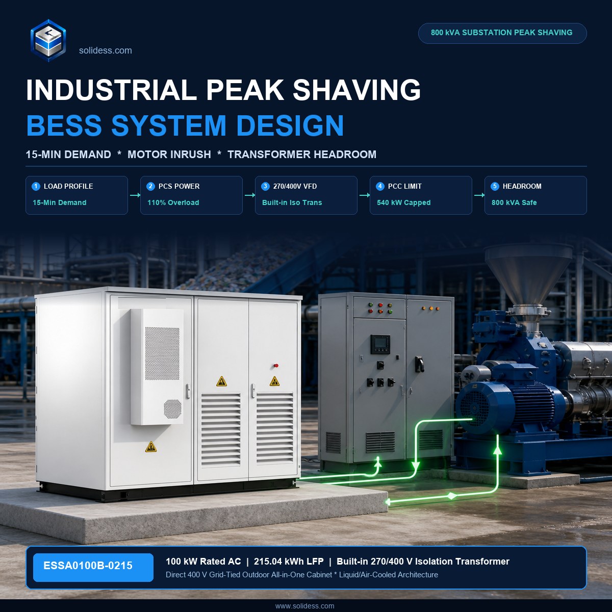
Heavy manufacturing facilities pay demand penalties every month because a single 15-minute production overlap drives the billing peak beyond the contracted threshold — yet most off-the-shelf battery cabinets trip offline the moment an injection moulding machine or air compressor starts. MegSolid ESSA0100B-0215 is the best-fit solution for this site because its 100 kW rated AC output, built-in 270/400 isolation transformer and 110% long-term overload rating absorb motor inrush currents, sustain full discharge for more than two hours, and eliminate the harmonic ground faults that take transformer-less cabinets offline.
- Select a 100 kW / 215 kWh Outdoor BESS: verify equipment specifications and enclosure ratings before designing factory peak shaving.
- Avoid transformer upgrades: evaluate whether behind-the-meter storage can bypass utility substation expansion queues.
- C&I system design: coordinate load profiles, power conversion and protection at the plant switchboard.
The Cost of Missed Peaks: Why 15-Minute Demand Windows Break Standard Storage
Utilities in Germany, the UK, South Africa and Australia calculate demand charges from the single highest average power reading recorded during any 15-minute window within the billing month. One reading. One month of penalties.
For a mid-size manufacturing facility operating at a normal load of 520 kW, a 12-minute overlap between two shift changes — during which three injection moulding machines restart simultaneously — can push the 15-minute average to 650 kW. At a demand charge rate of €18–€28 per kW per month, that 130 kW overshoot costs €2,340–€3,640 in a single billing cycle. Twelve months of the same pattern produces an annual penalty of €28,000–€43,700 that does not reduce energy consumption by a single kilowatt-hour.
The standard off-the-shelf response is to install a 50 kW / 50 kWh battery cabinet. On paper the math appears to work: 50 kW of shaving covers the surplus and the system costs less. In practice it fails for three reasons.
Discharge duration. A 50 kWh cabinet running at 50 kW is fully discharged in 60 minutes, assuming a perfect 100% depth of discharge — which no LFP system operates at in real conditions. At 90% DOD the usable window is 54 minutes. Manufacturing shift overlaps rarely resolve in under an hour when compressor banks, cooling towers and production lines re-stabilise after a start sequence. The cabinet exhausts its energy before the peak interval closes and the billing meter records the unsuppressed spike.
Motor inrush and harmonic pollution. The 15-minute demand interval begins the moment a peak is detected. During that same interval, variable-frequency drives and large induction motors generate 5th and 7th harmonic currents that travel back to the PCC. Transformer-less battery cabinets share a common ground with the factory distribution board. Harmonic zero-sequence currents and common-mode noise couple directly into the DC bus of the PCS, triggering insulation-monitoring relays and ground-fault protection. The cabinet trips. The peak shaving window is lost.
Overload at motor start. A 355 kW injection moulding machine draws 4–6× rated current for 200–400 milliseconds during direct-on-line starting. Even with a soft-starter, the inrush envelope reaches 200–250% of normal operating current. A 50 kW PCS with no overload headroom clips its output and may shut down on over-current protection at exactly the moment it is needed most.
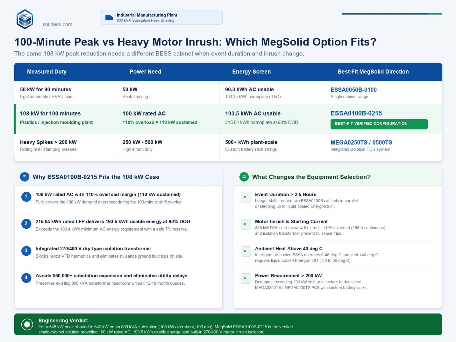
MegSolid ESSA0100B-0215 closes all three gaps simultaneously. Its 215.04 kWh rated battery energy, charged at 0.5C with a 1P240S, 280 Ah LFP configuration, delivers 100 kW continuously for more than two hours at 90% depth of discharge — 193.5 kWh of available AC energy, verified against the rated 215.04 kWh × 0.90 DOD = 193.5 kWh. That duration covers every realistic peak window in two-shift and three-shift manufacturing operations. Its 270/400 V built-in isolation transformer provides full galvanic separation between the 400 V factory grid and the battery DC bus, cutting the common-mode path that causes transformer-less cabinets to trip. Its 110% long-term overload rating means the PCS sustains 110 kW output — not 100 kW — during the critical first minutes of a motor-start sequence without protective shutdown.
No undersized cabinet covers a two-hour peak window with a harmonic-polluted factory supply. MegSolid ESSA0100B-0215 does.
Sizing Formula: How to Calculate kW, kWh and Delivered AC Energy
Selecting the wrong power or energy rating is the single most expensive mistake in industrial peak shaving procurement. Buying 30 kW too little means the peak is never fully suppressed. Buying 200 kWh too much means capital is locked into battery capacity that cycles at 20% utilisation and never pays back.
The correct sizing sequence runs in three steps.
Step 1 — Determine peak shaving power (kW). Pull twelve months of half-hourly or 15-minute interval demand data from the utility meter or building management system. Identify the highest recurring overshoot — the difference between the average recorded peak and the demand threshold the facility wants to maintain:
P_BESS = P_Peak, measured − P_Target threshold + P_Margin
The margin term accounts for metering latency, EMS response time and the brief moment the PCS ramps to full output. A 5–8% margin on the shaving power is standard for industrial sites with variable-frequency drives and reactive load banks.
Step 2 — Determine energy (kWh) at the target discharge duration.
E_Required = P_BESS × t_Window
The window is the longest continuous period during which the peak overshoot persists. For two-shift manufacturing with staggered startups, this is typically 90–130 minutes. Three-shift sites with 24-hour production cycles can sustain elevated demand for up to 150 minutes if air compressors, chillers and process heating overlap.
Step 3 — Verify the battery rated energy covers the required delivered energy at operating DOD.
E_Rated ≥ E_Required / DOD
LFP cells in the ESSA0100B-0215 — a 1P240S configuration of 280 Ah cells — are designed to operate at 90% depth of discharge in cyclic service. At 90% DOD, the 215.04 kWh nameplate delivers 193.5 kWh of usable AC energy per cycle, calculated as 215.04 × 0.90 = 193.5 kWh.
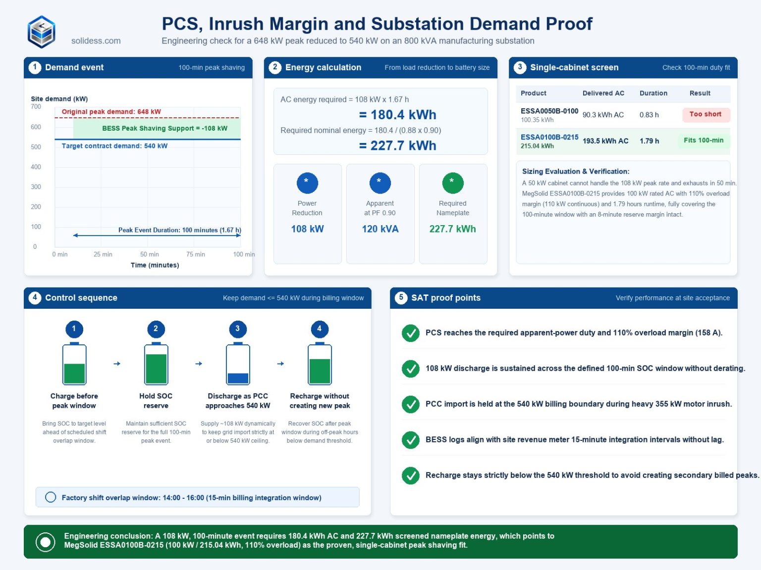
Worked example: injection moulding plant, 800 kVA substation, two-shift operation. A plastics manufacturer operates three 200-tonne injection moulding machines, two 75 kW air compressors and auxiliary HVAC on an 800 kVA substation limited to a contracted demand of 540 kW. Twelve months of 15-minute interval data show a recurring peak of 648 kW occurring during the 07:00–08:45 overlap window when the night-shift machines are still running hot while the day-shift machines restart.
| الإدخال | القيمة |
|---|---|
| Measured peak, highest recurring 15-min average | 648 kW |
| Target demand threshold | 540 kW |
| Raw shaving requirement | 108 كيلوواط |
| EMS response + metering margin (7%) | +7.6 kW |
| Required BESS rated AC output | 116 kW |
| Peak window duration | 100 minutes |
| الطاقة المطلوبة | 116 kW × 1.67 h = 193.7 kWh |
| ESSA0100B-0215 usable energy at 90% DOD | 215.04 × 0.90 = 193.5 kWh |
The numbers meet at the boundary — 193.5 kWh against 193.7 kWh — with virtually zero margin. This is precisely the crossover that tells a project engineer to select one ESSA0100B-0215 and configure the EMS threshold 5 kW conservatively, or to step up to two cabinets in parallel for a 50 kWh buffer.
The 110% long-term overload rating of the ESSA0100B-0215 is what makes the single-cabinet solution viable despite the tight energy margin. During the first 10 minutes of the discharge window — the most critical interval for preventing a demand spike — the cabinet can sustain 110 kW output rather than the rated 100 kW, giving the EMS additional headroom while the plant stabilises.
One parameter that eliminates most undersizing errors is the cycle-life floor. The ESSA0100B-0215 is rated for ≥5,000 cycles at 25°C, compared with ≥3,800 cycles for the smaller ESSA0030B-0055 and ESSA0050B-0055 cabinets. Daily peak shaving at two discharge events per day means approximately 730 cycles per year. At 5,000 cycles, the ESSA0100B-0215 battery sustains economically useful capacity for more than six years of daily double-cycling before reaching its end-of-life threshold — a warranty-level calculation that the 3,800-cycle smaller cabinets cannot match under the same duty.
For sites with rooftop solar, the MPPT input of the ESSA0100B-0215 accepts up to 1,000 V open-circuit PV voltage and covers a full-load MPPT range of 450–850 V, allowing the system to charge from PV during off-peak hours and discharge into peak shaving without requiring a separate solar inverter. Need a custom sizing calculation for your facility? Leave your business email and 15-minute load profile below to receive a free engineering sizing report and quotation.
Motor Inrush and Harmonic Loads: Why Built-in Isolation Transformers Are Non-Negotiable
The majority of C&I battery cabinets sold into manufacturing environments use a transformerless topology: the PCS connects directly to the factory 400 V distribution bus without galvanic separation between the AC grid and the DC battery string. This topology is lighter, cheaper and more efficient in clean-grid environments. In heavy manufacturing, it is a recurring source of nuisance trips, warranty disputes and failed commissioning sign-offs.
The harmonic coupling mechanism. Three-phase induction motors driven by variable-frequency drives produce current harmonics — primarily 5th (250 Hz), 7th (350 Hz) and 11th (550 Hz) orders — that propagate back through the distribution system to every point of common coupling on the same bus. In a transformerless PCS architecture, the battery DC bus shares a reference with the factory AC ground through the PCS power stage. The harmonic zero-sequence currents that circulate back through the neutral conductor generate a common-mode voltage between the DC bus positive terminal and the protective earth. When this common-mode voltage exceeds the threshold of the PCS insulation monitoring relay — typically 30–60 V in industrial-grade equipment — the insulation fault protection trips the PCS offline.
The fault clears when the drive load stabilises. The PCS reconnects. On the next motor start sequence the fault reappears. Field engineers on sites with no isolation barrier commonly log 8–15 nuisance trips per shift before diagnosing the root cause.
How a built-in isolation transformer eliminates the coupling path. The ESSA0100B-0215 includes an integrated 270/400 V isolation transformer between the PCS output stage and the factory 400 V bus. The transformer provides full galvanic separation: the factory-side neutral, earth and harmonic return currents have no electrical path to the battery DC bus or the PCS power stage. Common-mode voltages generated by VFD loads appear on the primary winding as a differential signal that attenuates through the transformer leakage inductance and does not reach the insulation monitoring circuit on the DC side.
The result is quantifiable in the grid-current distortion specification. The ESSA0100B-0215 delivers a grid-current THD of less than 3%, measured at the point of common coupling on the 400 V side of the isolation transformer. Under off-grid or backup operation with nonlinear loads — motor controllers, rectifiers, switching power supplies — the output voltage THD remains at or below 5%. These figures hold regardless of the harmonic environment upstream, because the transformer decouples the two sides.
Overload and inrush absorption. A 355 kW injection moulding machine on a soft-starter draws approximately 3.0–3.5× full-load current for 10–15 seconds during acceleration. At 400 V, full-load current for a 355 kW motor is approximately 640 A. The inrush envelope reaches 1,920–2,240 A on the motor terminals. The distribution transformer absorbs the bulk of this current; the peak shaving BESS is not asked to supply the motor start current directly. What it must do is maintain its peak shaving output without tripping during the voltage dip that accompanies the inrush event.
The ESSA0100B-0215 rated AC current is 144 A at 100 kW and 400 V. Its 110% long-term overload rating allows it to sustain 158 A continuously without triggering overcurrent protection. When the grid voltage dips by 5–8% during a large motor start, the PCS increases its output current to maintain the set-point power, staying within the 110% overload envelope. A cabinet with no overload margin clips its output at the rated current limit and allows the demand spike to pass through to the billing meter.
Why the ESSA0100B-0215 transformer ratio matters for the factory switchboard. The built-in transformer ratio of 270/400 V means the battery-side winding operates at 270 V while the factory-side winding delivers 400 V. This ratio is sized to match the DC bus voltage range of the 1P240S, 280 Ah LFP battery string, whose nominal voltage is 768 V and operating range spans 672–850 V. The PCS steps this down through its DC/AC conversion stage to the 270 V primary, and the transformer steps up to the 400 V factory grid. The factory electrical engineer connects the secondary terminals directly to the 400 V low-voltage switchboard — no additional step-up transformer, no external autotransformer, no additional panel space.
Compare this with a 100 kW transformerless cabinet on the same site. The installation requires a separately purchased isolation transformer rated at ≥110 kVA to provide the harmonic barrier, its own dedicated panel space, separate protection and metering, and a transformer efficiency loss of 1.0–1.5% on every kWh cycled. At 365 days × 193.5 kWh per cycle, the additional energy loss at 1.2% through an external transformer amounts to 850 kWh per year — at €0.15/kWh, an additional €127 per year in losses that the ESSA0100B-0215 avoids by integrating the transformer into the cabinet.
For facilities in Germany under VDE-AR-N 4100 or South Africa under NRS 097-2-1, an isolation transformer at the grid interconnection point is not optional — it is a grid-code requirement for behind-the-meter storage systems on certain network tariff structures. Procuring a BESS with an integrated isolation transformer satisfies this requirement without a separate procurement line item.
Industrial Sizing Matrix: Matching Factory Profiles to MegSolid Hardware
No single product covers every manufacturing load profile. The table below maps the four most common industrial demand scenarios to the MegSolid product that resolves each one, with the key parameters from the published product specifications that drive the decision and the engineering reason a smaller or simpler product would fall short.
| Factory profile | Peak shaving target | Recommended product | Critical parameters | Why a smaller product falls short |
|---|---|---|---|---|
| Light assembly / commercial building — HVAC, small CNC, packaging lines, 400 kVA substation | 25–45 kW, 1–2 h window | ESSA0030B-0055 | 30 kW rated AC, 55.296 kWh, 1C LFP, 100/400 isolation transformer, ≥3,800 cycles, 2,000 kg, IP54 | Adequate for light shaving; 1C rate means 55 kWh drains in 60 min at full power — windows beyond 60 min exhaust the cabinet before the peak clears |
| Mid-size manufacturing — injection moulding, die casting, precision machining, 630–1,250 kVA substation | 60–100 kW, 1.5–2.5 h window | ESSA0050B-0100 | 50 kW rated AC, 100.352 kWh, 0.5C LFP, 200/400 isolation transformer, ≥5,000 cycles, 2,400 kg, IP54 | Single cabinet covers 50 kW shaving with 2.0 h duration (90.3 kWh usable at 90% DOD) — appropriate where peak overshoot is ≤50 kW; two in parallel covers 100 kW |
| Heavy manufacturing — injection moulding ≥200 t, compressor banks, three-shift production, 800–2,000 kVA substation | 80–100 kW, 2–3 h window | ESSA0100B-0215 (primary recommendation for this scenario) | 100 kW rated AC, 144 A rated, 215.04 kWh, 0.5C, 1P240S / 280 Ah LFP, 270/400 isolation transformer, 110% long-term overload, ≥5,000 cycles, IP54, 2450 × 1550 × 2400 mm, 3,900 kg | The 55 kWh cabinets exhaust in under 60 min; the 100 kWh cabinet at 50 kW cannot shave an 80–100 kW overshoot; only the 215 kWh / 100 kW configuration covers the full window |
| High-cycle TOU / 24-hour processing — two full charge-discharge cycles per day, ambient 35–42°C, 1,000–2,000 kVA substation | 100–125 kW, dual-cycle daily dispatch | ميغ-سوليد إنرجون 261 | 125 kVA rated AC, 261.24 kWh, LFP 314 Ah, 1P260S, liquid cooling, operating range −20–55°C with derating above 45°C, up to 10 units in parallel, 1300 × 1350 × 2200 mm | Air-cooled ESSA cabinets are rated 0–45°C operating; sites above 40°C sustained ambient require liquid cooling to avoid thermal derating across two cycles per day |
| Large industrial park / heavy load above 200 kW — rolling mill, heavy press, ≥2,000 kVA substation | 200–500 kW, project-specific duration | MEGA0250TS or MEGA0500TS PCS paired with external battery strings | MEGA0250TS: 250 kW, 270/400 transformer, 97.3% max efficiency, 1,582 kg; MEGA0500TS: 500 kW, 315/400 transformer, 97.5% max efficiency, 2,665 kg | Integrated ESSA cabinet tops out at 100 kW per unit; above 200 kW continuous shaving power, a separate large-format PCS with independently sized battery strings is the correct architecture |
Selecting between single-cabinet and multi-cabinet configurations. The ESSA0100B-0215 supports parallel operation through the factory 400 V bus. Two cabinets connected to the same 400 V switchboard deliver 200 kW of combined peak shaving power and 430.08 kWh of combined rated energy. Three cabinets deliver 300 kW and 645.12 kWh. The EMS coordinates dispatch across all cabinets simultaneously using RS485 or TCP-IP communication. Each additional cabinet adds 3,900 kg and requires a 2,450 mm × 1,550 mm footprint.
The Energon 261 at 125 kVA and 261.24 kWh occupies a 1,300 mm × 1,350 mm footprint — smaller in plan area than a single ESSA0100B-0215 cabinet — and supports up to ten units in parallel. At full parallel scale, ten Energon 261 units deliver 1,250 kVA and 2,612.4 kWh in a compact arrangement suited to facilities with floor-space constraints but high energy throughput requirements.
Detailed ESSA0100B-0215 product selection criteria are covered in the product specification guide. Sites evaluating the step from air-cooled cabinet to liquid-cooled Energon should read choosing between liquid-cooled and air-cooled BESS for commercial projects before specifying thermal management.
Contact MegSolid engineering or submit an online inquiry with your 15-minute load profile and substation single-line diagram. Leave your email below to receive full technical specifications, 3D civil foundation drawings, electrical integration schematics, and factory-direct pricing.
Electrical Integration: Switchgear, Transformers and EMS Peak Limits
A BESS cabinet that is sized correctly on paper can still fail to suppress a billing peak if the switchboard connection, protection coordination and EMS polling architecture are not engineered as a matched system. The three most common integration errors on industrial sites — and how to avoid each one with ESSA0100B-0215 — are set out below.
Breaker and cable sizing for the 400 V connection. The ESSA0100B-0215 draws and delivers up to 144 A at rated output (100 kW at 400 V, three-phase) and up to 158 A at 110% overload. IEC 60364-5-52 requires that the upstream circuit breaker and cable assembly be rated for the continuous current including the overload envelope, with appropriate derating for the installation method and ambient temperature.
For a surface-mounted conduit installation at 35°C ambient with XLPE copper cable, the minimum conductor cross-section to carry 158 A continuously is 70 mm² per phase, with a 185 A-rated or larger moulded-case circuit breaker set to trip at 200 A instantaneous. The neutral conductor carries the imbalance current from the 3W + N + PE grid connection and should match the phase conductor cross-section on sites with significant single-phase loads. The protective earth conductor is sized to IEC 60364-5-54.
Do not upsize the breaker to eliminate nuisance tripping from motor inrush on the same bus. Motor inrush currents appear on the substation bus, not on the BESS feeder circuit. The BESS feeder breaker sees only the smooth 100–158 A DC-side-sourced AC output of the PCS — a well-shaped sinusoidal waveform at THD less than 3%.
Point of common coupling metering and CT placement. The EMS suppresses peaks by comparing the real-time demand reading at the PCC against the target threshold and dispatching the BESS to fill the gap. The metering CT must be installed on the main incomer of the 400 V low-voltage switchboard — the point where the utility supply and the BESS output combine before splitting to plant loads. Installing the CT downstream of the BESS connection point is the single most common commissioning error: the EMS sees only the net import after BESS discharge and cannot determine the actual demand the utility is recording.
For IEC 62053-21 class 1 metering, the CT ratio must be selected so that the secondary full-scale current (typically 5 A) corresponds to a primary current at least 10% above the highest expected fault-free demand. On an 800 kVA substation at 400 V, the maximum symmetrical current is 1,155 A. A 1,200/5 A CT ratio provides appropriate headroom.
The EMS receives CT data via RS485 or TCP-IP — both interfaces are available on the ESSA0100B-0215. The sampling interval should be configured at ≤200 ms so that the EMS detects the rising demand front within one sample period and issues the ramp command to the PCS with sufficient lead time to reach full output before the 15-minute averaging window registers the spike. At 200 ms sampling and a PCS ramp rate of 10–100% in under 500 ms, the total response latency from demand event to full PCS output is below 700 ms — well within the 900-second demand integration window.
Zero-export and import-limit interlock. Factories connected to networks that prohibit reverse power flow — South Africa under SSEG rules, UK sites under G98/G99, or German industrial tariffs under § 19 StromNEV import-limit conditions — must configure the EMS with a hard zero-export clamp. The ESSA0100B-0215 EMS supports adjustable power factor from 0.8 leading to 0.8 lagging and responds to import-limit set-points communicated over RS485 or TCP-IP. When net import approaches zero, the EMS ramps the discharge power down to match remaining plant load, preventing export without a hard trip.
BESS EMS priority logic for reserve, peak shaving and PV charging covers the dispatch hierarchy and the conditions under which zero-export overrides peak shaving. CT polarity and metering verification during BESS commissioning covers the site acceptance tests that confirm the EMS is reading the correct PCC current direction before the system is handed over.
Frequency and voltage operating window. The ESSA0100B-0215 AC interface operates within a grid voltage range of 320–460 V and frequency range of 45–55 Hz or 55–65 Hz. On 50 Hz networks, the operating band covers the full allowable frequency deviation under IEC 61000-2-2 without disconnection. The cabinet remains online during the brief voltage dips — typically 5–12% of nominal for 200–500 ms — that accompany large motor starts on the same substation, maintaining its peak shaving output through the entire inrush transient.
Upgrade Triggers: When to Move from ESSA0100B to Parallel Cabinets, Energon 261 or MEGA TS PCS
The ESSA0100B-0215 is the correct single-unit answer for the factory profile described throughout this article. Three conditions change that answer and require a different product path.
Trigger 1 — Peak overshoot exceeds 120 kW or discharge window exceeds 2.5 hours. At 110% overload, a single ESSA0100B-0215 sustains 110 kW output indefinitely. For a facility with a sustained peak overshoot of 130–200 kW, or a peak window lasting beyond 2.5 hours (requiring more than approximately 300 kWh of delivered energy), a single cabinet is insufficient. The correct response is to add a second or third ESSA0100B-0215 cabinet in parallel on the same 400 V bus.
Two cabinets deliver 200 kW rated and 430.08 kWh rated (386.9 kWh usable at 90% DOD). Three cabinets deliver 300 kW and 645.12 kWh rated (580.6 kWh usable). Each additional cabinet requires its own 200 A MCCB feeder, 2,450 mm × 1,550 mm outdoor footprint and 3,900 kg structural pad. Before committing to a third cabinet, evaluate whether the Energon 261 offers a better footprint-per-kWh ratio: its 1,300 mm × 1,350 mm cabinet holds 261.24 kWh — 21.5% more energy than the 215.04 kWh ESSA in 36% less plan area.
Trigger 2 — Sustained ambient temperature above 40°C or two full discharge cycles per day. The ESSA0100B-0215 is rated for operating temperatures of 0–45°C and uses intelligent air cooling. Sites where the cabinet enclosure ambient temperature regularly exceeds 40°C — outdoor installations in Saudi Arabia, Nigeria, Southern Spain or the UAE, or indoor installations near process heat sources — will experience accelerated capacity fade if the cabinet cannot shed heat fast enough at peak ambient.
The Meg-Solid Energon 261 uses liquid cooling and is rated for operating temperatures from −20°C to 55°C, with derating commencing above 45°C. For sites with sustained ambient above 40°C, the liquid-cooled Energon 261 maintains stable thermal management across both a morning and evening discharge cycle. Its 125 kVA rated AC output and 261.24 kWh capacity cover the same peak shaving window as the ESSA0100B-0215, with additional thermal headroom that prevents mid-cycle capacity reduction.
Liquid-cooled BESS maintenance: coolant, leak detection and derating checks covers the ongoing requirements specific to the Energon platform.
Trigger 3 — Peak shaving power requirement exceeds 200 kW or the project requires a standalone PCS with separately specified battery strings. Two ESSA0100B-0215 cabinets cover 200 kW. Above this threshold, the project architecture shifts to a dedicated PCS: the MEGA0250TS at 250 kW or the MEGA0500TS at 500 kW, paired with separately procured battery strings sized to the project energy requirement.
The MEGA0250TS delivers 250 kW rated, carries a built-in 270/400 isolation transformer, achieves 97.3% maximum efficiency, and fits in a 1,200 mm × 800 mm × 2,050 mm cabinet at 1,582 kg. The MEGA0500TS scales to 500 kW at 97.5% maximum efficiency, with a 315/400 isolation transformer and a 1,600 mm × 1,050 mm × 2,050 mm footprint at 2,665 kg. Both MEGA TS units support 110% long-term overload and automatic on-grid/off-grid switching. Their IP rating is IP21 — an indoor installation product, unlike the IP54-rated ESSA outdoor cabinet. The MEGA TS is a PCS only, requiring a separately supplied and commissioned battery system.
Transformer-integrated versus modular energy storage inverter selection covers the full architecture comparison between integrated and standalone PCS options. BESS for motor starting: PCS sizing and demand-interval guide covers the PCS selection methodology for extreme inrush loads above 200 kW.
Ready to eliminate monthly demand penalties and confirm your substation headroom with MegSolid ESSA0100B-0215? Leave your business email and site parameters below to connect with a MegSolid technical sales engineer for a dispatch simulation, battery lifecycle assessment, and formal quote.
الأسئلة الشائعة
How fast does an industrial peak shaving BESS respond to a demand spike?
The ESSA0100B-0215 ramps from standby to full 100 kW output in under 500 milliseconds when the EMS detects a rising demand front. With a CT sampling interval of 200 ms at the PCC, the total response time from demand event to full PCS output is below 700 ms — fast enough to intercept the rising slope of a motor-start peak well before the 15-minute billing average registers the overshoot.
Can a 100 kW BESS shave a peak caused by a 355 kW motor starting?
The BESS does not supply the motor start current — the distribution transformer and grid absorb the inrush. What the ESSA0100B-0215 does is maintain its 100 kW discharge output through the voltage dip that accompanies the motor start, preventing the combined factory load from exceeding the contracted demand threshold during the inrush transient. Its 110% long-term overload rating (110 kW sustained) provides additional margin during the stabilisation period after the motor reaches operating speed.
Why does an industrial peak shaving battery need a built-in isolation transformer?
Variable-frequency drives and large induction motors generate harmonic currents that create common-mode voltages between the AC neutral and the DC battery bus in transformerless PCS designs. These voltages trigger insulation monitoring relays and cause nuisance trips. The ESSA0100B-0215 includes a 270/400 V isolation transformer that provides full galvanic separation between the factory 400 V grid and the battery DC bus, eliminating the common-mode coupling path. The grid-side output THD remains below 3%.
What is the difference between a 15-minute and 30-minute demand interval for peak shaving sizing?
A 15-minute interval requires the BESS to sustain its rated output for the full 15-minute window plus any overlap period. A 30-minute interval doubles the energy requirement for the same shaving power. At 100 kW shaving power, a 15-minute window requires a minimum of 25 kWh of usable energy; a 30-minute window requires 50 kWh. The ESSA0100B-0215 at 193.5 kWh usable covers both interval structures with substantial margin, making it suitable for utilities in Australia (30-minute NEM intervals), the UK (half-hourly settlement) and South Africa (30-minute Eskom notified maximum demand).
How many hours of battery duration are needed for manufacturing peak shaving?
Two to three hours covers the realistic range for two-shift and three-shift manufacturing operations. Single-shift facilities with a clearly bounded startup overlap may need only 60–90 minutes of duration. The ESSA0100B-0215 at 193.5 kWh usable and 100 kW rated output delivers 1.935 hours at full power — sufficient for most two-shift manufacturing scenarios. Sites with peak windows exceeding 2.5 hours should evaluate parallel ESSA0100B-0215 cabinets or the Energon 261.
Does daily peak shaving degrade the battery faster than solar self-consumption cycling?
The LFP cells in the ESSA0100B-0215 (1P240S, 280 Ah) are rated for ≥5,000 cycles at 25°C. At one full cycle per day, the battery reaches 5,000 cycles in approximately 13.7 years. At two cycles per day — morning peak shaving plus evening TOU load shifting — the calendar life reduces to approximately 6.8 years. Solar self-consumption typically produces 0.3–0.7 effective cycles per day depending on solar irradiation and load matching, giving a longer calendar life but with lower annual kWh throughput than dedicated peak shaving.
Can the ESSA0100B-0215 provide emergency backup power during a grid outage?
Yes. The ESSA0100B-0215 supports both on-grid and off-grid operation. During a grid outage, the system transitions to off-grid mode and supplies critical loads from the battery. Under off-grid operation with nonlinear loads, the output voltage THD remains at or below 5%. The system reverts automatically to on-grid mode and resumes peak shaving when grid power is restored. BESS system design for C&I sites covers the protection coordination required to isolate backup loads from the main distribution board.
What cable and breaker sizing is required for the ESSA0100B-0215 400 V connection?
At 100 kW rated output, the ESSA0100B-0215 draws 144 A at 400 V three-phase. At 110% overload, the maximum continuous current is 158 A. For a surface-mounted XLPE copper cable installation at 35°C ambient, a minimum 70 mm² phase conductor and a 185 A-rated or larger MCCB set to 200 A instantaneous trip is appropriate. The grid connection is 3W + N + PE. Confirm cable derating factors and breaker coordination with the site electrical engineer against the applicable national wiring rules.
Can multiple ESSA0100B-0215 cabinets be paralleled as factory production expands?
Yes. Additional cabinets connect to the same 400 V low-voltage switchboard through individual MCCB feeders. The EMS coordinates discharge across all cabinets via RS485 or TCP-IP. Two cabinets deliver 200 kW rated and 430.08 kWh rated energy. Each cabinet requires a 2,450 mm × 1,550 mm footprint and a 3,900 kg civil pad. Above three cabinets in parallel, evaluate whether the Energon 261 or an ESSC containerised system offers a better energy-per-footprint and lifecycle cost outcome for the expanded load.
When should a factory upgrade from ESSA0100B-0215 to the liquid-cooled Energon 261?
Three conditions trigger the upgrade: sustained ambient temperature above 40°C, two or more full discharge cycles per day, or a peak shaving energy requirement above 215 kWh per cycle. The Energon 261 uses liquid cooling and is rated from −20°C to 55°C (with derating above 45°C), making it the correct choice for hot-climate installations and high-throughput TOU arbitrage applications. Its 125 kVA rated AC output and 261.24 kWh capacity cover the same peak shaving window as the ESSA0100B-0215 with additional thermal stability. Liquid-cooled versus air-cooled BESS selection guide provides the full comparison framework.
How does industrial peak shaving work under UK half-hourly settlement tariffs?
UK commercial and industrial customers on half-hourly metered supplies (Profile Class 00) face Maximum Import Capacity charges and Triad demand penalties based on the three highest half-hourly system demand periods in the winter settlement period. A BESS configured to suppress the facility's gross import during the October–February Triad window can eliminate Triad charges entirely if the EMS is configured with a Triad alert feed and a dedicated backup SOC reserve. The ESSA0100B-0215 at 193.5 kWh usable covers a 30-minute half-hour settlement period at 100 kW output with a 28.5 kWh energy margin above the minimum required.
Can a BESS reduce Eskom notified maximum demand charges in South Africa?
Yes. South African C&I customers on Eskom Megaflex or Miniflex tariffs pay a Notified Maximum Demand charge based on the highest recorded 30-minute kVA demand in the billing month, plus an Actual Maximum Demand penalty if the site exceeds its registered NMD by more than 10%. A BESS configured to hold the 30-minute kVA reading below the registered NMD eliminates the AMD penalty and gradually reduces the NMD registration — lowering the fixed capacity charge in subsequent billing periods. The ESSA0100B-0215 operates on Eskom's standard 400 V three-phase grid connection and meets the IP54 coastal and inland environmental requirements.
How do German manufacturing facilities calculate peak shaving under § 19 StromNEV?
German industrial customers eligible for reduced grid fees under § 19 StromNEV must demonstrate an atypical grid load profile: their highest load during the annual high-load hours must remain below 20% of their annual peak load to achieve maximum fee reduction. A BESS configured to cap the facility's demand during published high-load hour windows maintains the atypical profile threshold and preserves eligibility for the § 19 reduction. High-load hours are published annually by the German TSOs; the EMS must be programmed with these windows and maintain a dedicated SOC reserve throughout each period. The ESSA0100B-0215 frequency range of 45–55 Hz covers the 50 Hz Continental European synchronous grid and its AC voltage range of 320–460 V spans the permissible EN 50160 tolerance band for 400 V networks.