When a regional utility grid trips while 15 tonnes of ductile iron sits at 1,550°C inside a medium-frequency coreless induction furnace, the melting supply drops out immediately along with the closed-loop cooling water pumps and the hydraulic tilting unit. Only a few inches of rammed silica or alumina refractory separate the liquid metal bath from the hollow water-cooled copper induction coil. With the circulation pumps stopped, heat from the bath conducts outward through the lining into stagnant coil water.
Without backup power, coil water approaches boiling within minutes, risking vapour lock, coil insulation damage, or a coil breach that allows water to contact molten metal. If the outage continues for hours and the furnace cannot be tilted to pour, the bath solidifies into a frozen charge that must be chipped out with pneumatic hammers, usually destroying the refractory lining and often damaging the copper coil.
A battery energy storage system (BESS) in a foundry or stamping plant performs two engineering functions: it isolates and powers the critical furnace cooling and tilting bus during grid outages, and it shaves the overlapping melt-cycle and press-line peaks that set monthly utility demand charges. Because thyristor (SCR) furnace rectifiers inject heavy current harmonics and voltage notching onto the plant bus, commissioning a BESS in a melt shop also requires specific harmonic and impedance design so the battery inverters do not trip offline when the furnaces hit full power.
Key Takeaways
- Separate critical safety backup from peak shaving: A dedicated critical bus keeps coil cooling pumps, power-supply cooling, hydraulic tilting units and channel furnace inductors running during grid outages, while the remaining battery capacity shaves melt-cycle peaks and shifts energy across time-of-use windows.
- Account for SCR harmonics and voltage notching before ordering hardware: Six- and 12-pulse furnace rectifiers distort the bus waveform enough to make standard commercial grid-following inverters lose phase-locked loop (PLL) synchronisation. A pre-design power quality survey, medium-voltage connection point and validated PCS settings prevent nuisance trips.
- Coordinate IEEE 519 filtering and reactive power: A BESS supplies dynamic reactive power (kvar) and low-THD output current, and should be coordinated with detuned capacitor banks or active harmonic filters rather than treated as a standalone harmonic filter for heavy 6-pulse loads.
- Match press-shop storage to the pulse timescale: Sub-second servo press strokes are best buffered by capacitor or flywheel storage on the press DC bus, whereas plant-level 15-minute demand peaks, flywheel restarts and surplus regenerative energy belong on a plant-level BESS.
- Install battery cabinets outside the melt shop: Conductive cast-iron and graphite dust, radiant heat and water-based fire suppression systems require placing liquid-cooled IP54 cabinets outdoors away from melting and pouring bays.
Preventing Frozen Charges and Coil Failures During Induction Furnace Outages
Water-Cooled Copper Coils Under Loss of Flow
A coreless induction furnace consists of a hollow, water-cooled copper coil surrounding a refractory crucible. During melting, circulating deionised or treated water removes both the $I^2R$ electrical losses in the copper turns and the thermal energy conducted outward from the 1,550°C bath through the refractory lining.
When a power outage interrupts the furnace supply, electrical heating in the coil stops, but conductive heat soak from the molten bath continues. Depending on furnace tonnage, lining wear and bath level, stagnant water inside the coil passages can reach boiling temperatures within a few minutes. Boiling inside the coil leads to:
- Steam pockets and vapour lock that block water circulation even after pumps restart;
- Overheated coil turn insulation and refractory grout, shortening coil life;
- Copper coil rupture, which can introduce pressurised water behind the refractory lining.
Furnace manufacturers require an independent emergency cooling supply (such as an elevated gravity tank, an engine-driven pump or a city-water changeover valve) that opens automatically on power loss. A BESS does not replace the furnace OEM's mandatory emergency cooling system; it keeps the primary closed-loop pumps and heat exchangers running continuously through grid interruptions so the backup water system remains a secondary safeguard.
The Frozen Charge Problem
When an outage extends beyond a short interruption, the unheated bath begins solidifying from the crucible walls inward. Allowing a full charge to freeze inside a coreless furnace results in:
- Multi-day furnace downtime while crews break out the solid metal block;
- Complete refractory lining replacement and potential copper coil damage;
- Scrapped heats and missed delivery schedules.
Instead of attempting to supply megawatts of melting power from batteries, the operational procedure during a prolonged outage is to tilt the furnace and pour the liquid metal into transfer ladles, pig moulds or an emergency run-off pit while viscosity is still low. That requires uninterrupted AC power to the hydraulic tilting pump station, melt-deck lighting and fume extraction.
In channel (core-type) holding and pouring furnaces, the failure mode is even stricter: if molten iron solidifies inside the narrow inductor throat, the inductor assembly is typically ruined. Channel furnace inductors must be maintained on holding power (typically 100–300 kW per inductor) throughout an outage.
Segregated Critical-Bus Architecture
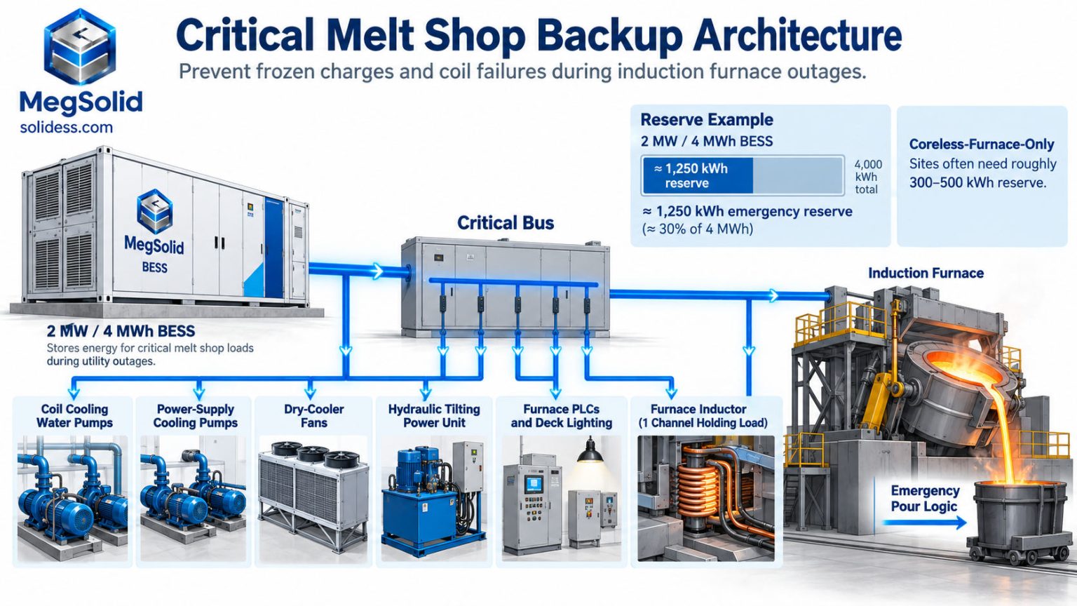
Rather than backing up the 3–10 MW main melting bus, a foundry BESS feeds a segregated Critical Melt Shop Bus. When the incoming utility feeder fails, the BESS isolates the critical bus and restores voltage within 20 milliseconds, keeping auxiliary motors spinning without dropping out their contactors while the main melting converters shut down safely.
| Critical Load | Operational Purpose | Typical Power Rating |
|---|---|---|
| Coil cooling water pumps (closed loop) | Maintains flow through furnace coils to prevent boiling and vapour lock | 15–45 kW |
| Power-supply water pumps | Cools SCR thyristors and DC-link capacitors after trip | 5–20 kW |
| Evaporative tower / dry-cooler fans | Rejects heat from the closed deionized water loop | 10–40 kW |
| Hydraulic tilting power unit | Enables controlled emergency pour into ladles or pig moulds | 30–75 kW (intermittent) |
| Channel furnace inductors (where installed) | Prevents metal freeze in the inductor throat | 100–300 kW+ |
| Furnace PLCs, emergency deck lighting, fume hood | Safe operator visibility and monitoring during emergency pour | 10–30 kW |
Typical ranges shown for illustration; size every project from the furnace OEM electrical schedule and measured motor currents.
Three engineering requirements apply to the critical bus:
- Hard SoC floor in the EMS: Configure the energy management system to lock a minimum State of Charge reserve (for example, 30% SoC) that daily peak-shaving dispatch cannot discharge.
- Soft-started pump and hydraulic motors: Equip cooling pumps and hydraulic pack motors with VFDs or soft starters so motor re-acceleration stays within the inverter's overload envelope (MegSolid's 80–125 kW modular PCS provides 110% continuous output and 120% for 1 minute).
- Scheduled black-start transfer tests: Test the islanding transfer switch under live pump load during planned maintenance shutdowns at least once a quarter.
Sizing the Emergency Reserve: Worked Example
Consider a melt shop operating two medium-frequency coreless furnaces and one channel holding furnace:
| Critical Load Item | Running Power | Required Backup Duration | Required Energy |
|---|---|---|---|
| Coil & converter cooling pumps + dry-cooler fans | 80 kW | 5.0 h | 400 kWh |
| Hydraulic tilting unit (emergency pour cycle) | 55 kW | 0.5 h | ≈30 kWh |
| Furnace PLCs, deck lighting, fume extraction | 20 kW | 5.0 h | 100 kWh |
| Channel furnace inductor (holding power) | 180 kW | 4.0 h | 720 kWh |
| Total critical backup energy (before losses) | ≈1,250 kWh |
On a 2 MW / 4 MWh foundry BESS, reserving 1,250 kWh (roughly 32% of nominal capacity) guarantees full auxiliary and holding backup while leaving 2.75 MWh available for daily demand peak shaving and tariff arbitrage. A melt shop with coreless furnaces only (no channel holding furnace) requires roughly 300–500 kWh of reserve capacity. Confirm the required post-pour coil cooling duration against your furnace manufacturer's manual.
Foundry Peak Demand Reduction: Taming the Melt Cycle
Anatomy of an Induction Furnace Load Curve
A batch melt in a coreless induction furnace follows a steep step profile:
- Cold charge and bulk melting: 40–60 minutes at 90–100% rated MW;
- Deslagging, spectroscopic sampling and alloy trimming: power drops to 10–20% holding level;
- Superheating and tapping: brief high-power boost to pouring temperature, followed by power-off or low hold during tapping.
A single furnace produces a predictable sawtooth demand curve. When a melt shop runs two, three or four furnaces alongside sand mullers, automated moulding lines, shot-blasting turbines and air compressors, individual melt cycles drift into overlap. If two furnaces draw full melting power during the same 15- or 30-minute utility integration window even once in a billing month, that overlap sets the peak kW or kVA demand charge for the entire month.
Even in melt shops with parallel power-sharing converters or production scheduling rules, a late scrap charge, a chemistry hold or a ladle delay regularly pushes furnaces into simultaneous peak draw.
Automated Melt-Cycle Peak Shaving and TOU Shifting
Connected to the main substation current transformers (CTs) and furnace status inputs, the MegSolid EMS tracks rolling 15-minute integrated demand. When overlapping furnaces push plant import toward the target demand cap, the BESS discharges to supply the excess load, then recharges during deslagging and pouring pauses or overnight off-peak tariff hours.
Because utility demand meters average power over 15 or 30 minutes, the BESS only needs to shave the overlapping peak above your demand threshold rather than carry the entire melt shop. Where overlapping melts push site demand 2 MW above baseline for 30–45 minutes, a 2 MW / 4 MWh system (including the critical-bus safety reserve) covers both the peak-shaving window and emergency backup.
For multi-megawatt foundry installations, up to 10 units of MegSolid's 261 kWh / 125 kVA liquid-cooled C&I cabinet can be paralleled into 1.25 MW / 2.6 MWh blocks, or configured as containerised systems from our 55 kWh – 5 MWh BESS portfolio. On melt-shop projects above 1 MW, we typically step the BESS up to the plant's medium-voltage (MV) bus through a dedicated isolation transformer to decouple the inverters from low-voltage furnace rectifier distortion.
IEEE 519 and the "Dirty" Foundry Busbar: Why Standard Inverters Trip
What SCR Furnace Power Supplies Do to Plant Voltage
Medium-frequency induction furnaces rectify 50/60 Hz AC power to DC using 6-pulse, 12-pulse or 24-pulse thyristor (SCR) or diode bridges before inverting to medium frequency (typically 150 Hz to 1,000 Hz). Thyristor rectification affects the supply bus in two ways:
- Characteristic harmonic currents: A 6-pulse bridge draws harmonic currents at orders $h = 6k \pm 1$ (5th, 7th, 11th, 13th, etc.), often producing current total harmonic distortion ($\text{THD}_i$) of 15–30% on the furnace feeder. A 12-pulse converter fed by a dual-secondary phase-shifting transformer ($\Delta\text{-Y}-\Delta$) cancels most 5th and 7th harmonics, leaving the 11th, 13th, 23rd and 25th orders.
- Line voltage commutation notching: During each commutation interval when current transfers between thyristor pairs, two phases are briefly bridged through the source inductance. This cuts sharp notches out of the AC voltage sine wave, producing extra zero-crossings and high-frequency $dv/dt$ spikes, and pushing low-voltage bus $\text{THD}_v$ to 8–12%.
Why Commercial Grid-Following Inverters Lose Lock
Standard commercial BESS inverters designed for office buildings or retail solar use a basic synchronous-reference-frame phase-locked loop (SRF-PLL) to track utility voltage angle and frequency. When connected to a bus with deep commutation notches and high 5th/7th harmonic distortion, a basic PLL suffers from phase-angle jitter and false zero-crossing detection. As soon as the induction furnaces ramp up to full melt power, the inverter reports a grid frequency or waveform fault and trips offline.
Industrial converters operating in heavy metalworking plants require frequency-adaptive, sequence-separating PLL algorithms (such as Dual Second-Order Generalised Integrator PLLs, DSOGI-PLL, or moving-average prefilters) along with widened voltage/frequency ride-through windows and output LCL filters damped against background harmonics.
Three Engineering Steps Before Commissioning a Foundry BESS
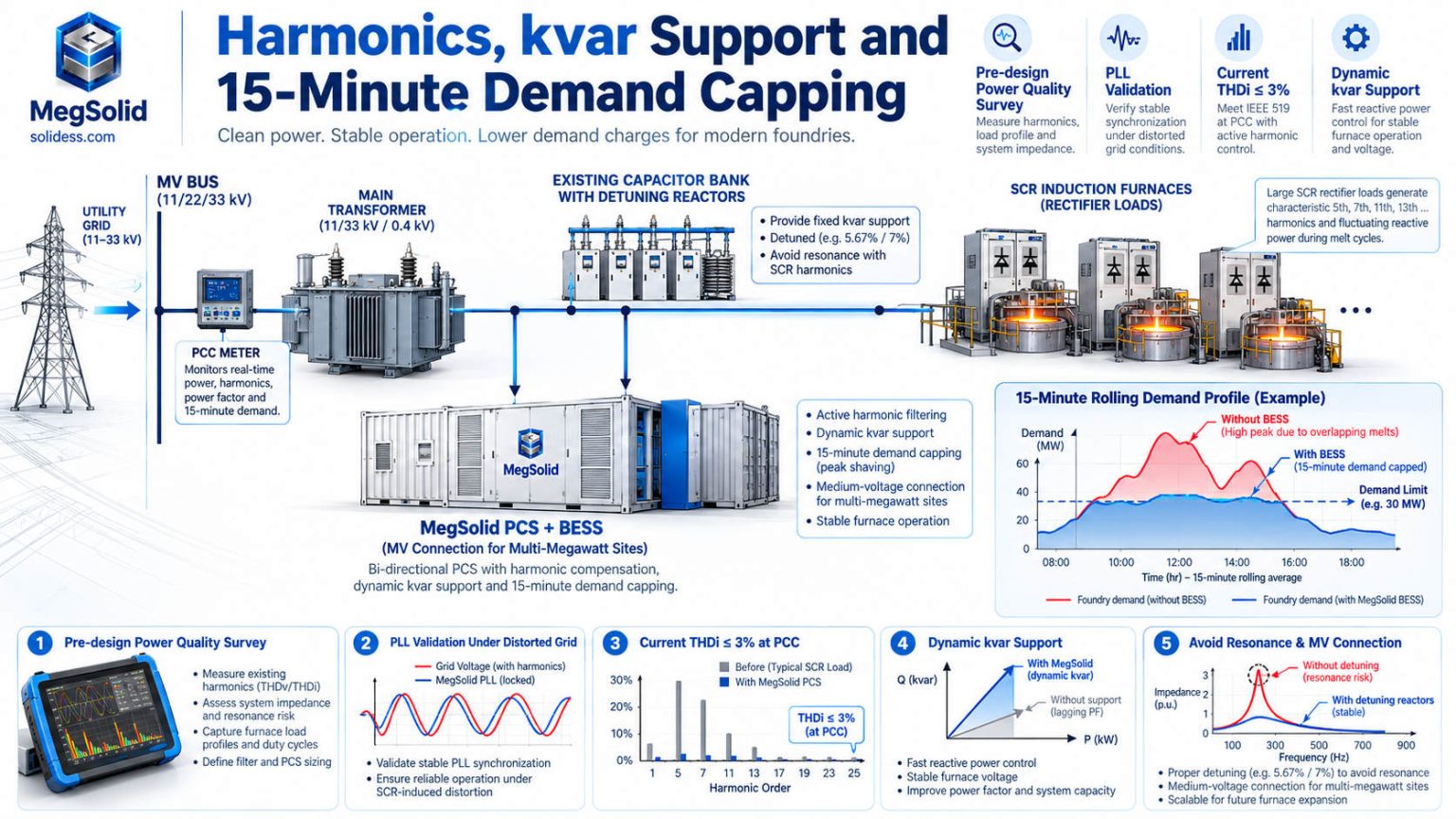
1. Conduct a 7-day Class A power quality survey. Before finalising the single-line diagram, log voltage and current waveforms at the proposed Point of Common Coupling (PCC) and melt-shop bus using an IEC 61000-4-30 Class A analyser across full melting cycles. Record harmonic orders up to the 50th, voltage notch depth, interharmonics and rapid voltage changes.
2. Connect at the medium-voltage bus via a dedicated transformer. Avoid connecting a BESS directly to the low-voltage secondary of a furnace rectifier transformer. Connecting to the plant's MV switchgear through a dedicated BESS step-up transformer places two transformer leakage impedances between the SCR bridges and the battery inverters, attenuating commutation notches and high-order voltage harmonics.
3. Validate PCS protection and PLL parameters against site waveforms. Configure PLL filtering bandwidth and grid protection thresholds against the recorded harmonic spectrum, and verify stability during hot commissioning with all furnaces at 100% power.
IEEE 519 Harmonic Limits at the PCC
IEEE 519-2022 evaluates harmonic distortion at the Point of Common Coupling (PCC) between the industrial facility and the utility grid rather than on internal furnace feeders:
| IEEE 519-2022 Metric at PCC | Limit |
|---|---|
| Voltage THD ($\text{THD}_v$), bus voltage $\le 1\text{ kV}$ | 8.0% total (5.0% any single harmonic) |
| Voltage THD ($\text{THD}_v$), $1\text{ kV} < V \le 69\text{ kV}$ | 5.0% total (3.0% any single harmonic) |
| Current Total Demand Distortion ($\text{TDD}$) | 5.0% to 20.0%, scaled by short-circuit ratio $I_{SC}/I_L$ |
Whether a foundry's current distortion violates IEEE 519 depends on the utility's short-circuit stiffness ($I_{SC}/I_L$) at the meter.
Role of the BESS in Reactive Power and Harmonic Management
A foundry BESS supports power quality at the PCC in two ways:
- Dynamic four-quadrant reactive power (kvar): Parallel-tuned SCR furnaces draw lagging reactive power that varies across the melt cycle, while series-tuned IGBT supplies operate near unity power factor. MegSolid PCS units adjust power factor continuously from −1 to +1, injecting leading reactive power during melt cycles to maintain utility power factor above penalty thresholds (typically 0.90 or 0.95) and lowering billed kVA demand.
- Low-distortion current injection: MegSolid PCS units maintain current $\text{THD}_i \le 3%$ at rated output, diluting overall current TDD percentages at the PCC when discharging.
Note that active harmonic filtering (APF) is a separate converter function from real and reactive power dispatch. While some converter platforms offer harmonic-cancelling firmware, cancelling 5th through 13th harmonics from multi-megawatt 6-pulse furnaces consumes significant inverter current capacity and requires high-bandwidth current loops with dedicated CT placement. For melt shops with heavy 6-pulse SCR distortion, the most reliable engineering solution is pairing the BESS with detuned passive harmonic filters or a dedicated Active Harmonic Filter (AHF) sized from the site power quality study.
Avoiding Capacitor Bank Parallel Resonance
Foundries that install standard switched power-factor capacitor banks on a bus with SCR furnaces frequently experience blown capacitor fuses, bulging cans or transformer overheating. A capacitor bank ($Q_C$) in parallel with the supply transformer's short-circuit capacity ($S_{SC}$) forms a parallel LC tank circuit with a natural resonant harmonic order of:
$$h_r \approx \sqrt{\frac{S_{SC}}{Q_C}}$$
For example, on a 2,500 kVA transformer with 6% impedance ($S_{SC} \approx 41.7\text{ MVA}$) connected to a 1,500 kvar capacitor bank, the resonant frequency sits at $h_r \approx \sqrt{41.7 / 1.5} \approx 5.27$, right on top of the 5th harmonic injected by a 6-pulse induction furnace. Instead of correcting power factor safely, the capacitor bank amplifies 5th-harmonic currents across the bus.
To prevent parallel resonance, fixed capacitors in foundries must be fitted with detuning series reactors (typically 7% or 14% reactors, shifting resonance to the 3.8th or 2.7th order on a 50 Hz grid) or replaced by converter-based reactive compensation from the BESS PCS and SVG equipment. Always include existing capacitor banks in the pre-installation harmonic impedance study.
Metal Stamping: Press Pulses, Regenerative Energy and Plant-Level Peaks
Electrical Signature of Servo and Mechanical Press Lines
In automotive and industrial metal stamping shops, a 1,500- to 2,500-ton tandem servo press line operates at 10 to 20 strokes per minute. During each 1-to-2-second forming stroke, main servo drives draw a multi-megawatt power pulse; as the ram decelerates past bottom dead centre, the servo motors regenerate power back onto the drive DC bus.
Conventional mechanical flywheel presses draw lower steady-state power during continuous stamping, but pull heavy, sustained inrush currents for 30 to 90 seconds whenever operators accelerate the heavy flywheels after a die change, shift break or feeder outage. Starting several press lines in the same 15-minute window creates a plant-wide demand peak.
Matching Storage Hardware to the Pulse Timescale
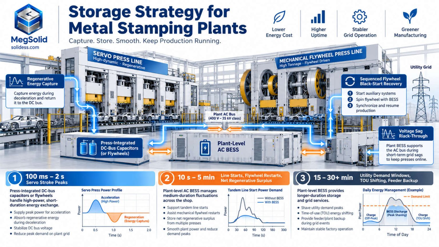
Stamping energy transients occur across three distinct timescales, each suited to a different storage medium:
| Timescale | Electrical Event | Appropriate Storage Architecture |
|---|---|---|
| 100 ms – 2 seconds | Individual servo press stroke peak and ram deceleration pulse | Press-integrated DC-bus capacitor banks or kinetic flywheels (standard on modern servo press lines) |
| 10 seconds – 5 minutes | Mechanical flywheel startups, tandem line starts, net regen surplus | Plant-level AC BESS with fast CT feedback |
| 15 – 30+ minutes | Utility billing demand windows, TOU tariff shifting, feeder backup | Plant-level AC BESS |
Attempting to absorb every 4-second servo stroke directly in a lithium battery is poor engineering practice: a 15-stroke-per-minute press running two shifts executes over 3.5 million cycles per year. Sizing an AC battery system for 3 MW sub-second pulses inflates PCS cost and subjects the cells to unnecessary high-rate throughput and heat generation.
Four High-Return BESS Functions in Stamping Plants
- 15-minute utility demand capping: The BESS shaves the combined demand of press lines, flywheel startups, compressed-air headers and robotic spot-welding cells during peak production windows.
- Capturing surplus regenerative energy: On older press lines that still dissipate braking energy as heat in rooftop resistor banks, retrofitting active front-end (AFE) regenerative drives returns braking energy to the plant AC bus. When background factory load is light, the BESS absorbs that regenerated power and re-releases it on subsequent load peaks rather than tripping reverse-power relays or exporting unpaid power to the grid.
- Voltage sag ride-through for transfer automation: Voltage dips on industrial feeders trip sensitive multi-axis transfer robots and vision systems between presses, causing die crashes or line stops. The BESS supports bus voltage during utility sags.
- Sequenced flywheel black-start recovery: Following a power outage, the EMS staggers mechanical press flywheel starts and supplies the acceleration energy from the battery so the restart does not set a new monthly utility demand peak.
Built for the Foundry: Conductive Dust, Radiant Heat and Fire Safety
Conductive Metallic and Carbon Dust
Foundry and press-shop air contains conductive cast-iron dust from fettling and grinding, flake or nodular graphite from iron inoculation, fine silica sand from shakeout conveyors, and die-lubricant oil mist. If drawn inside an air-cooled battery rack or inverter cabinet, conductive iron and graphite particles bridge high-voltage creepage and clearance distances across busbars and PCB terminals, causing tracking and arc-flash faults.
Siting the BESS Outside the Melt Shop
Every safety and reliability requirement in a foundry points to placing the BESS outdoors, outside the melt and pouring buildings:
- Dust isolation: Locate cabinets upwind of sand reclamation towers, shot-blasting exhausts, cupola or furnace baghouses and grinding bays;
- Thermal separation: Keep battery enclosures away from radiant heat sources such as holding furnaces, ladle preheaters and cooling conveyors;
- Molten metal and water separation: Industrial BESS cabinets include internal water-based fire suppression piping; never install water-piped battery enclosures inside a molten-metal bay where water discharge could contact spilled iron or slag;
- Emergency access: Provide unobstructed perimeter access for fire trucks in accordance with NFPA 855.
Sealed Liquid Cooling and Cell Safety
MegSolid's Energon 261 kWh liquid-cooled cabinet houses its LFP battery modules inside an IP54 outdoor enclosure cooled by a sealed internal liquid coolant loop, operating in ambient temperatures from −20°C to 55°C (derating above 45°C). Because shop air is never blown across the battery modules, conductive foundry dust cannot accumulate on cell terminals. Only the external chiller radiator coil contacts outside air and can be cleaned during routine external maintenance. Any indoor PCS cabinets should be installed inside a positively pressurised, filtered electrical switchgear room.
At the cell level, lithium iron phosphate (LFP) chemistry and MegSolid's hybrid solid-state battery platform provide high thermal stability without oxygen release. Each Energon cabinet incorporates multi-sensor smoke, VOC and thermal detection, Novec 1230 clean-agent suppression and a dry-pipe water fire suppression interface.
Property insurance compliance: Heavy industrial underwriters such as FM Global evaluate BESS installations under FM Global Property Loss Prevention Data Sheet 5-33 alongside NFPA 855 and UL 9540 / UL 9540A fire test documentation. Request our certification and layout package early so your insurer's loss-prevention engineer can review setback distances before civil works begin.
Foundry and Stamping BESS ROI: Four Value Streams
Illustrative case: An automotive casting and stamping facility operating two 3 MW coreless induction furnaces, one channel holding furnace and a tandem press shop, deploying a 2 MW / 4 MWh liquid-cooled BESS (with 1.25 MWh reserved for the critical furnace bus and 2.75 MWh active for peak shaving and arbitrage).
| Value Stream | Engineering Basis | Illustrative Annual Benefit |
|---|---|---|
| 1. Peak demand charge shaving | 1.8–2.0 MW reduction in monthly 15-min peak demand at $8–15/kW-month | $170,000 – $360,000 / year |
| 2. Time-of-use tariff arbitrage | ~2.5 MWh/day shifted from peak to off-peak tariff across 300 operating days ($0.06–0.10/kWh spread) | $45,000 – $75,000 / year |
| 3. Reactive power & kVA reduction | Continuous power-factor correction at the PCC, eliminating utility reactive penalties and reducing kVA demand | $20,000 – $60,000 / year (+ avoided capacitor/SVG CapEx) |
| 4. Avoided frozen charge / coil damage | Uninterruptible backup for coil cooling pumps, tilting hydraulics and channel inductors during feeder outages | $100,000 – $500,000+ saved per prevented outage event |
Financial figures are illustrative and depend on local tariff structures and feeder reliability. On tariff savings alone (Streams 1–3), a 2 MW / 4 MWh medium-voltage BESS typically achieves simple payback in 3 to 5 years. On industrial feeders where utility outages occur once or twice every few years, factoring in avoided furnace freeze-up and production losses brings effective payback into the 2 to 3 year range.
When presenting the business case to your finance team, model the project in two scenarios: a conservative baseline counting only contracted tariff savings (demand charges, TOU spread and power factor), and a risk-adjusted case weighting the cost of a melt-shop blackout by your historical utility outage frequency.
FAQ
Will constant pulsing from presses or furnace ramps wear out the battery?
Battery cycle life depends on Depth of Discharge (DoD), C-rate, cell temperature and total MWh throughput. For servo stamping presses, sub-second stroke pulses should be buffered by the press's own DC-link capacitors or flywheels rather than the plant BESS. Using the plant BESS to cap 15-minute utility demand windows and absorb net regenerative surpluses subjects the liquid-cooled LFP cells to one or two predictable partial cycles per day, keeping degradation well within a 10-to-15-year industrial design life.
How do we size the emergency backup reserve for induction furnace cooling and tilting?
Obtain the emergency electrical load list from your furnace OEM: closed-loop coil cooling pumps, converter cooling pumps, heat-exchanger fans, hydraulic tilting power pack, channel furnace inductors and PLC controls. Multiply each continuous load by the required post-outage cooling time (typically 3 to 5 hours) and add the 20-to-30-minute hydraulic emergency-pour cycle. Melt shops with coreless furnaces only usually require 300–500 kWh of locked SoC reserve; shops with channel holding furnaces typically require 1.0–1.5 MWh.
Can a BESS operate alongside 6-pulse or 12-pulse SCR induction furnaces without tripping or resonance?
Yes, when designed around three steps: perform a 7-day Class A harmonic and load survey during full melting operations, connect the BESS to the medium-voltage bus through a dedicated step-up transformer to isolate it from low-voltage commutation notches, and run a harmonic impedance study that accounts for existing power-factor capacitor banks before commissioning.
Will installing a BESS bring our foundry into IEEE 519 compliance?
A BESS improves power quality at the Point of Common Coupling by supplying dynamic reactive power (kvar) and low-THD real power, which reduces kVA demand and avoids resonance issues associated with un-detuned capacitor banks. However, where 6-pulse SCR rectifiers generate heavy 5th and 7th harmonic currents that exceed IEEE 519 TDD limits at the utility meter, the BESS should be paired with detuned passive filters or a dedicated Active Harmonic Filter (AHF) sized from your busbar harmonic sweep.
Does a BESS replace our furnace's mandatory emergency cooling system?
No. Keep the furnace manufacturer's required emergency cooling system (gravity water tank, backup engine pump or mains-water changeover valve) fully operational. The BESS keeps the primary closed-loop deionized cooling pumps and hydraulic tilters running seamlessly during grid outages so you can empty the furnace safely without having to dump raw emergency water through the coil.
Conclusion: Engineering Storage for Melt Shops and Press Lines
Foundries and metal stamping plants place heavier demands on energy storage than standard commercial buildings: multi-megawatt melt overlaps, SCR commutation notches, high-inertia press restarts, conductive shop dust, and the severe financial cost of losing cooling water to a full induction furnace.
By separating a dedicated critical bus for furnace cooling and tilting, connecting peak-shaving storage at medium voltage after a full harmonic survey, and siting sealed liquid-cooled cabinets outside the melt shop, heavy manufacturers can cut monthly demand charges while protecting their furnaces against grid blackouts.
Planning a peak-shaving or furnace backup project? Contact MegSolid's engineering team to schedule a free busbar harmonic and load-profile assessment. Send us your 12-month utility bills, furnace and press electrical schedules, and plant single-line diagram; within 24 hours we will provide a preliminary BESS sizing report, critical-bus schematic and datasheets for our solid-state energy storage systems.