

Production-line shutdowns can turn the factory's BESS and rooftop PV into an immediate reverse-power risk at the PCC. MegSolid ESSA0100B-0215 is the right choice for this 70 kW duty: 100 kW output, 215.04 kWh energy, integrated EMS and built-in isolation give the project one decisive platform for peak shaving and zero-export control.
- Integrated C&I cabinet: ESSA combines the battery, cabinet-side energy management and AC isolation in one product platform.
- Coordinated zero-export control: the installed PCC meter and PV command path extend ESSA into the site-wide control loop.
- Traceable acceptance: the final decision follows installed evidence, not a controller-screen claim.
Choose ESSA0100B-0215 for the 70 kW Factory Duty

The factory needs to cut purchased power, absorb more rooftop PV and prevent reverse power at a restricted grid connection. Those demands call for enough discharge power, usable energy and a control platform that can coordinate the battery with the rest of the site.
Choose MegSolid ESSA0100B-0215. The example factory requires 70 kW of battery discharge before a production-line shutdown. ESSA supplies 100 kW rated AC output, covering that duty with 30 kW of nameplate power margin. Its 215.04 kWh nominal battery energy provides the capacity foundation for sustained peak shaving, while the operating schedule defines how that energy is used across the factory's demand window.
The battery, integrated EMS and built-in isolation transformer are packaged in one IP54 outdoor cabinet.
Its 400 V AC interface, RS485/TCP-IP communications and access to load, battery, grid, diesel-generator and PV signals give the EPC a clear platform for connecting the factory's energy assets.
| MegSolid configuration | Customer pain point | Direct customer benefit |
|---|---|---|
| 100 kW rated AC power | Factory requires 70 kW of battery discharge | Covers the full duty with 30 kW of nameplate power margin |
| 215.04 kWh nominal energy | Peak shaving must continue beyond the initial load step | Provides the energy base for a sustained discharge window |
| Integrated EMS and multi-energy access | Battery, PV, grid and generator signals must be coordinated | Consolidates cabinet-side management on one communications platform |
| Built-in isolation transformer | Separate AC-isolation equipment adds cost and coordination work | Brings isolation into the ESSA cabinet package |
| IP54 enclosure and intelligent air cooling | Outdoor equipment must manage dust exposure and continuous heat rejection | Delivers an outdoor-ready enclosure with integrated thermal management |
ESSA0100B-0215 gives this factory the required power class, the energy base for peak shaving and the cabinet-side controls needed for site engineering. The customer gets one MegSolid storage platform instead of having to reconcile separate battery, PCS, EMS, isolation and outdoor-cabinet packages.
Send MegSolid the factory's load profile, PV capacity and required discharge window. The customer receives an ESSA0100B-0215 configuration proposal covering cabinet settings, the PCC measurement boundary and the external PV-control interfaces needed before SAT.
The SAT Must Prove Zero Export at the PCC
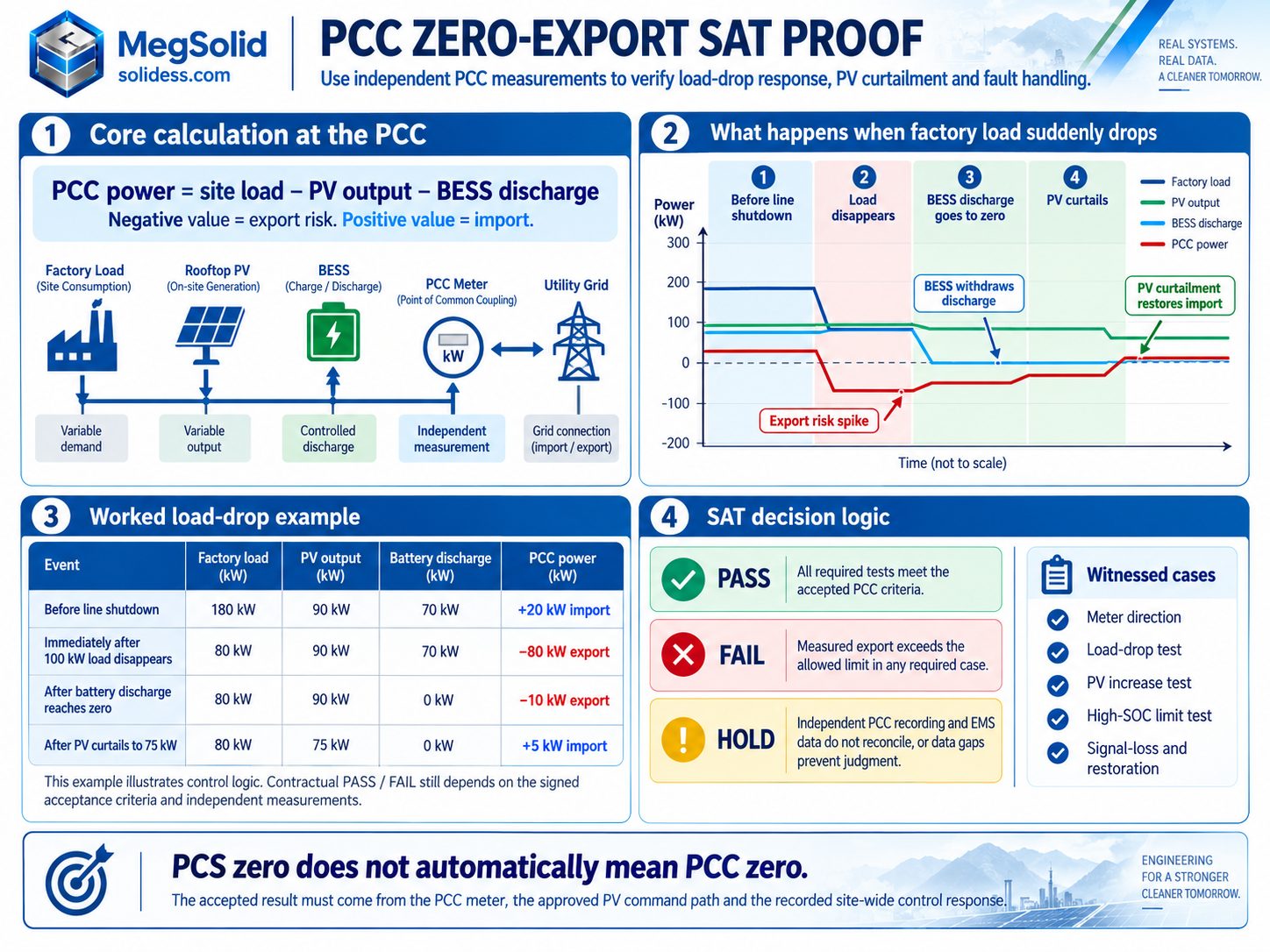
Product selection settles the cabinet choice. The BESS zero-export site acceptance test then proves that the installed controls keep the PCC inside the signed export boundary when factory load changes, PV output rises or a control signal fails.
Independent measurement has to represent the utility boundary. Battery and PV controls must act together, and every required normal and fault case must meet the signed export criterion. Zero discharge at the PCS is not proof of zero export at the PCC. ESSA provides the integrated battery-side platform; the installed PCC meter and authorized PV-control path complete the site-wide loop.
Define the Acceptance Boundary Before Testing
Record the agreement's measurement point, total three-phase or applicable phase-specific obligation, allowed transient envelope and failure state before testing. The signed SAT can release only the operating mode and conditions actually accepted; it does not replace usable-energy, outage-backup or other grid-connection approvals.
Verify the Installed Measurement and Control Interfaces Before Live Testing
Start with the approved single-line diagram. Mark the contractual measurement point, utility incomer, CTs, PV feeders, battery feeder, major switchable loads and every controlled source. The ESSA feeder meter can show correct cabinet response while the incomer is still exporting because of PV.
| Installed interface | Site check | Evidence that must survive handover |
|---|---|---|
| PCC measurement | Confirm CT location, ratio, polarity, phase pairing, active-power sign and meter quality | As-built drawing, instrument identity and comparison with a reference reading |
| ESSA cabinet | Match ESSA0100B-0215, serial number, rated 400 V AC interface, integrated isolation provision, software revision, available charge/discharge power and BMS limits | Confirm that the proposed cabinet-side configuration matches the delivered equipment; preserve synchronized command-versus-actual trends |
| PV inverter or plant controller | Identify which device can reduce PV output and how an accepted curtailment command is acknowledged | Register/command map, measured PV power and response record |
| EMS and site network | Verify setpoint ownership, data freshness, command priority and fallback states | Approved control narrative, signal map and alarm record |
| Witness instrumentation | Confirm independent PCC recording, clock agreement, sample resolution and sign convention | Meter accuracy, logging interval, timestamp basis and raw trace |
Verify import and export direction with a safe, approved low-power charge/discharge check before attempting a large step. Reversed CT wiring or a mistaken software sign can make a dangerous controller response look successful. The end-to-end CT and meter-direction commissioning method supports this check. The SAT sheet only needs the instrument identity, conditions and accepted result from that procedure.
Put Every Control Signal on One Time Base
ESSA's EMS and communications create the traceable cabinet-side signal plan: capture PCC active power, site load, PV power, BESS AC power, SOC, permitted charge/discharge power, setpoints, command acknowledgments, actual responses, breaker status, alarms and link quality on one time base.
That visibility helps the EPC separate ESSA response from site-meter and third-party PV behavior during commissioning. Set recorder resolution against the approved transient measurement method; a minute-averaged dashboard can hide a short reverse-power excursion. The BESS SCADA point-list specification establishes the broader tag-definition context.
Keep Grid Protection Intact During Every Switching Event
The authorized grid connection, protection and anti-islanding functions remain intact throughout testing. Factory operations and the electrical safety team must approve every switching event; use a controllable test load or scheduled process change when interrupting production would be unsafe.
Execute the Full Zero-Export Commissioning Matrix
The approved test schedule determines the exact cases and initial conditions. In a PV-plus-BESS factory, the matrix below covers failure paths that a steady "0 kW export" screenshot cannot prove. Select the applicable rows, record the chosen operating conditions and execute all cases required by the connection agreement and SAT procedure. One load-drop run cannot stand in for the whole matrix.
| Witnessed case | Test action | Measured proof | Failure revealed |
|---|---|---|---|
| Meter direction and steady operation | Change battery power at a stable load, then return to the contracted export target | Reference PCC instrument and EMS agree on sign and settled power | Wrong CT orientation, scaling or measurement point |
| Sudden factory load reduction | Reduce an approved major load with PV and BESS initially producing | Peak export, duration, actuator commands and final PCC value | Discharge persists after demand disappears |
| PV generation increase | Introduce the approved PV output step or controlled generation change at stable load | PV ramp, BESS action, curtailment and PCC trace | Battery and PV controls conflict or react too slowly |
| Combined load/PV variation | Apply the safe, approved combined event | PCC trend throughout the transition and recovery | Individual loops pass but combined sources export |
| High SOC or limited battery charging | Repeat a surplus-generation case with the approved high-SOC/charge-limited state | BMS charge limit, PV reduction or other authorized sink, and PCC trend | Export control depends on unavailable battery absorption |
| Concurrent peak-shaving or import-limit mode | With low SOC or a discharge limit, run the applicable overlapping control mode | Zero-export priority remains active while the unavailable discharge request is limited | Priority conflict, integrator wind-up or unstable command switching |
| Meter or command-link failure | Simulate each approved signal fault separately, without bypassing protection | Quality flags, timeout, alarm, actual fallback power and PCC trend | Stale discharge, uncontrolled PV or unsafe automatic restart |
| Restoration | Reinstate the relevant healthy signal or controller using the approved sequence | Stable PCC result, controlled re-enable and no second export event | Return-to-service causes another transient |
Establish trustworthy metering first. Prove ordinary operation next, then introduce dynamic steps and authorized fault conditions.
ESSA provides the integrated EMS platform, command visibility and cabinet-side response needed for those tests. The installed PCC meter and external PV controller complete the site loop. That division gives the EPC a commissioning basis tied to measured site behavior instead of a generic "zero-export ready" claim.
Do not open an energized CT secondary or bypass protection; use approved, equipment-compatible test methods.
EPRI's December 2023 power-control testing presentation to the New York State ITWG describes load steps, generation steps, combined changes and abnormal-signal cases. It is a technical research reference, not a universal utility acceptance schedule or a MegSolid response-time specification.
BESS load-drop test: the battery stops, but the site still exports
Consider an illustrative factory with one ESSA0100B-0215 connected to a 400 V board. The figures below are calculated three-phase active power at one consistent AC measurement boundary. Grid import is positive; battery discharge is positive.
| Event | Factory load | PV output | Battery discharge | PCC power |
|---|---|---|---|---|
| Before line shutdown | 180 kW | 90 kW | 70 kW | +20 kW import |
| Immediately after 100 kW load disappears, before controls respond | 80 kW | 90 kW | 70 kW | −80 kW export |
| After battery discharge reaches zero | 80 kW | 90 kW | 0 kW | −10 kW export |
| After PV curtails to 75 kW | 80 kW | 75 kW | 0 kW | +5 kW import |
PCC power = site load − PV output − BESS discharge in this example. The calculated −80 kW excursion illustrates the uncontrolled instant; it is not an actual site measurement. With battery discharge withdrawn, solar still exceeds the factory load by 10 kW. Curtailing PV by 15 kW produces an illustrative +5 kW import target, not a standard tolerance or a default MegSolid setting.
The 70 kW duty uses 70% of ESSA0100B-0215's 100 kW rating, leaving 30 kW of nameplate power margin. The selected cabinet already covers the required discharge power. This SAT case verifies the control sequence at the PCC, not the need to change the BESS. The EMS dispatch-priority logic explains how export control interacts with reserve, peak shaving and solar charging.
Keep the Load-Drop Evidence Needed for the Verdict
Retain the load-change timestamp, highest measured reverse power under the agreed sign convention, time and energy outside any specified threshold, BESS withdrawal and PV curtailment traces, and the settled PCC reading. Whether the excursion passes depends entirely on the signed criteria and valid measurements, not on the example's calculated 80 kW.
PV curtailment SAT: prove the available actuator at high SOC
During a controlled PV increase, ESSA's integrated EMS can reduce battery discharge, request charging where permitted and coordinate the authorized PV-control path. Its multi-source access gives the project one cabinet-side foundation for battery, PV, grid and generator signals. At high SOC, the approved PV actuator manages the surplus that the battery can no longer absorb. Capture requested and measured power so the commissioning record proves the complete response at the PCC.
The PV charging-priority analysis connects available battery absorption with generation management. In the SAT, its role is practical: establish whether the chosen control path still works when the battery cannot accept the assumed charging power.
Signal-loss and restoration cases: prove the installed fallback
Test the approved loss-of-meter, EMS-to-PCS and EMS-to-PV signals separately. Record the ESSA-side EMS/PCS response alongside the third-party PV response and independent PCC measurement; the integrated cabinet alone cannot prove the external fallback. Record stale-data detection, alarms, actual power and the safe state specified by the project. Stopping the PCS may still leave surplus solar generation. Witness restoration as well: an obsolete discharge command or control oscillation can undo the benefit of a correctly selected power class.
These are grid-connected export-control tests. Utility outage and backup transition belong to a separate operating state; the grid-tied BESS outage boundary distinguishes anti-islanding and permitted backup operation without confusing them with a zero-export PASS.
Use Independent PCC Measurements to Decide PASS, FAIL or HOLD
The signed connection agreement and SAT schedule must define the measurement location, permitted export limit or prohibition, any transient allowances, relevant window, uncertainty treatment and recovery criterion. Apply those values to the independent PCC trace, and examine equipment commands to explain the result. EMS display zero is not enough for a PASS.
| Result observed | Decision | Next action |
|---|---|---|
| All required tests meet their respective accepted PCC criteria; fault responses and restoration are traceable | PASS for the tested zero-export operating scope | Sign each case and identify the accepted software/settings revision |
| Measured export exceeds a specified magnitude, duration or energy limit in any required case | FAIL for that case | Diagnose, correct and repeat the failed and affected tests |
| Battery command goes to zero but PV export remains beyond the accepted limit | FAIL when the exceedance is confirmed; otherwise HOLD pending valid evidence | Check PV control authority, available sinks and the reference meter |
| Independent PCC recording and EMS disagree, with no trustworthy resolution | HOLD; no valid PASS | Reconcile CTs, measurement point, sign, scaling and timestamps; repeat as required |
| Data gaps prevent assessing a required transient | HOLD; no valid PASS | Restore suitable recording and rerun the affected event |
| Test passes only through a manual override not included in approved normal operation | FAIL against an automatic-control requirement, or HOLD while its status is resolved | Restore the approved automatic path and retest |
Quantify the PASS/FAIL Evidence
Quantify the result using the specified method: maximum reverse-power magnitude, elapsed time outside the accepted boundary, exported energy if the agreement requires it, time to settled operation, alarm state and any repeated excursion during recovery. Fast controller traces and a slow revenue meter can describe the same event differently; use the agreed instrument and time resolution for the contractual judgment.
The signed output is a case-by-case acceptance record covering only the required cases completed at accepted conditions. The PCC reverse-power test releases only the documented zero-export operating scope. It does not certify battery energy capacity, backup operation or every other plant function.
Retest Every Changed Function Before Operating Release
Retain the original failed traces, meter identity, control settings, software revisions and witness comments. Fixing the defect is only half the job. The new result has to be tied to the configuration that will actually operate.
Retest the Function That Changed
Meter or CT correction calls for direction verification and repetition of affected dynamic cases. Changing PV curtailment calls for both PV-rise and load-drop tests.
Changing SOC-limit handling reopens the relevant boundary cases. Changing the fallback or firmware calls for signal-loss and recovery retesting, plus any normal cases affected by the revised logic.
The retest matrix must follow the changed function; repeating one convenient event does not clear unrelated cases.
Keep Functional SAT Separate From Capacity and Performance Acceptance
The BESS factory-acceptance record identifies the delivered hardware and software baseline. The FAT, SAT and performance-acceptance distinction prevents a zero-export functional PASS from being mistaken for usable-energy or long-term performance approval.
The final signed file links each required case to its initial condition, independent PCC trace, commands, feedback, alarms, acceptance threshold, verdict and retest reference. The operating release names the controller revision, enabled mode and restrictions. Where utility permission or a separate grid-connection study is required, site SAT does not replace those approvals.
Send MegSolid the failed trace, cabinet revision and current signal map. MegSolid will identify the ESSA-side settings involved and return a defined interface boundary plus the site-meter and PV-control items the EPC must include in the retest plan.
FAQ
FAQ
What must the purchase contract define before zero-export SAT?
It should name the PCC measurement point, export target, allowed transient envelope, required cases, instrument method, controlled assets, fallback state, witness roles and retest rules. Suppliers cannot price or prove an undefined site obligation.
Where should the acceptance measurement be taken?
Use the connection point or point of reference named in the agreement. The instrument must see every governed load, PV inverter and BESS path; a battery-feeder meter cannot prove site-wide zero export.
Which cases should the EPC include in the SAT schedule?
Include meter-direction verification, steady operation, load steps, PV steps, combined changes, high-SOC charging limits, applicable concurrent control modes, signal failures and recovery. The signed connection requirements decide which cases are mandatory.
What recorder and data should the buyer require?
Require an independent PCC measurement with suitable accuracy and sampling, synchronized with site load, PV power, BESS power, SOC, limits, commands, feedback, alarms and communications quality. Raw trend files should remain part of the handover record.
Can a short reverse-power pulse pass?
Only when its measured magnitude, duration or energy remains inside the signed acceptance envelope. Cabinet power rating and another project's response time do not create a universal allowance.
Who should own PV curtailment during zero-export operation?
The control narrative must identify the device authorized to curtail each PV inverter or plant controller and the party responsible for commissioning that path. ESSA provides the battery-side EMS and multi-source integration foundation; the approved PV controller completes the site-wide zero-export loop.
Is one load-drop test enough for procurement acceptance?
No, unless the signed procedure expressly limits the obligation to that event. One PASS does not prove the response to rising PV, unavailable battery charging, combined changes or a failed PCC signal.
Must the SAT include a high-SOC condition?
Yes when battery charging is one of the export-control actuators. The test must show the approved PV-curtailment or alternative action when the BMS removes the expected charging headroom.
What should be reviewed before changing the selected BESS configuration?
Keep the selected ESSA0100B-0215 when the factory's duty remains 70 kW and the failed trace points to metering, command timing or PV curtailment. Review a different equipment class only when the sustained power or discharge-duration requirement itself changes.
What should the final zero-export handover file contain?
Include the approved procedure, as-built measurement boundary, instrument details, controller and software revisions, initial conditions, raw traces, commands, feedback, alarms, case verdicts, corrective actions, retest references and the exact operating scope released.
What does a BESS zero export SAT test prove?
It proves that the installed meter, BESS and applicable PV controls keep measured PCC export inside the signed criterion during the required normal, limit and fault cases. EMS screens showing zero are not sufficient evidence.
Why is ESSA0100B-0215 recommended for the example factory?
Its 100 kW AC rating covers the stated 70 kW battery duty with 30 kW of nameplate margin. The 215.04 kWh nominal energy, integrated EMS, built-in isolation, IP54 enclosure and intelligent air cooling give the factory a complete cabinet-side platform for peak shaving and zero-export integration.
Does a zero-export SAT PASS prove backup operation or usable battery capacity?
No. Zero-export control, grid-loss backup and usable AC energy have different equipment states, measurements and acceptance boundaries. The signed release must name the function that was actually tested.