
Most guides on charging batteries solar setups still describe a single 100W panel clipped to a 12V car battery. Homeowners and installers sizing a 16 kWh home bank or a 100 kWh light-commercial system need engineering-grade calculations: array sizing, MPPT voltage windows, real-time battery current limits, and charge temperature boundaries.
This guide works through those calculations using MegSolid's Energy Storage Hybrid Inverters (3 kW to 6 kW single-phase G2S-C models and 30 kW to 50 kW three-phase R-series models) and our 51.2V 314Ah Residential Energy Storage Systems (MEG-Solid-512314FL1 and MG 512314). Every product figure below is cross-checked against MegSolid's official specifications, and every assumption used in an illustrative calculation is explicitly labelled.
Solar Panels for Battery Charging: Sizing Formula & Reference Matrix
Sizing solar panels for battery charging starts with calculating the daily PV energy needed to replenish the battery's planned cycling depth, before adding daytime household or facility loads:
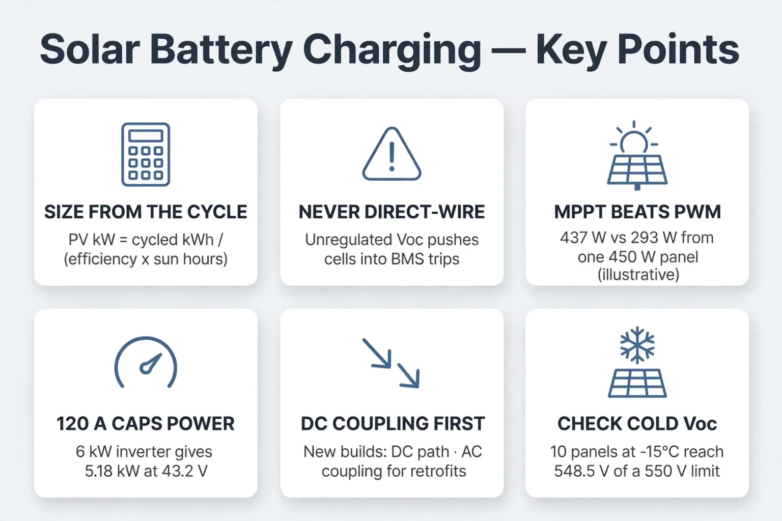
PV array power for battery recharge (kW) = Usable battery energy (kWh) / [Charge-path efficiency × Peak Sun Hours (h)]
Where:
- E_usable is the daily DC energy cycled in the battery (nameplate energy multiplied by the target Depth of Discharge, DoD).
- η_charge is the PV-to-battery charging path efficiency (accounting for MPPT conversion, DC cabling, and cell charge acceptance). Table 1 uses an illustrative assumption of 0.90.
- H_PSH is the site's average daily Peak Sun Hours. Table 1 uses an illustrative 4.5 h.
Table 1: Illustrative Solar Recharging Sizing Matrix (80% DoD, 4.5 PSH, Assumed 90% Charge Efficiency)
| Storage Configuration | Cycled Energy (at 80% DoD) | Candidate Inverter (Confirm BMS Compatibility by Model) | PV Array for Battery Recharge Only | Inverter Max PV Input & MPPT Window |
|---|---|---|---|---|
| 1 x MEG-Solid-512314FL1 (51.2V / 314Ah / 16.07 kWh) | 12.86 kWh | R5KL1DA-G2S-C (5 kW AC / 100A max battery current) or R6KL1DA-G2S-C (6 kW AC / 120A) | 3.17 kW (8 × 450W panels) | 7.5 kW / 9 kW (550V max PV; 100–430V MPPT) |
| 2 x MG 512314 (2 × 16,076 Wh; verify voltage limit) | 25.72 kWh | R6KL1DA-G2S-C (6 kW AC / 120A max battery current; confirm voltage & BMS rules) | 6.35 kW (15 × 450W panels) | 9 kW (2 MPPT trackers; 16A max per MPPT) |
| Compatible HV battery stack, 100 kWh class (150–800V) | 80.0 kWh | R30KH3 (30 kW AC / 33 kW max charge; 80A × 2 inputs) | 19.75 kW (44 × 450W panels) | 45 kW (4 MPPT trackers; verify max PV V on datasheet) |
| Compatible HV battery stack, 150 kWh class (150–800V) | 120.0 kWh | R50KH3 (50 kW AC / 55 kW max charge; 80A × 2 inputs) | 29.63 kW (66 × 450W panels) | 75 kW (4 MPPT trackers; verify max PV V on datasheet) |
Engineering Boundary Notes on Table 1:
- Candidate Inverters Require Model-Specific BMS and Voltage Verification: The inverters listed in Column 3 are candidate pairings based on voltage class and power scale. Final pairing must be confirmed per project against the exact battery model's operating voltage window, charge cutoff limits, and approved BMS communication protocol list.
- Nameplate PV Input Margin vs. Deliverable AC Load Power: On Row 2 (2 x MG 512314 with R6KL1DA-G2S-C), subtracting the 6.35 kW battery-recharge array from the inverter's 9 kW maximum PV input leaves 2.65 kW of nameplate STC PV array capacity margin. Engineers must note that 2.65 kW is solely the remaining DC module installation headroom under standard test conditions, not continuous AC power available to daytime loads, which depends on real-time irradiance, cell temperature derating, and inverter conversion efficiency.
- Separating Rated AC Power from Battery Current Limits: On the single-phase G2S-C series, 5 kW (R5KL1DA-G2S-C) and 6 kW (R6KL1DA-G2S-C) represent the inverter's rated power ceiling, while battery-side current is separately capped at 100A and 120A respectively. Because DC charging power equals real-time battery voltage multiplied by charging current (P_DC = V_bat × I_bat), actual battery charging power varies with State of Charge (SOC) and cannot be assumed to stay fixed at 5 kW or 6 kW across the entire voltage curve.
- High-Voltage Battery Compatibility on the R-Series: While the three-phase R30KH3, R40KH3, and R50KH3 inverters support a 150V to 800V DC battery voltage range across two 80A inputs, compatibility with any specific standard lithium-ion or hybrid solid-state battery rack must be confirmed by verifying the stack's full-SOC voltage range, current limits, and BMS protocol handshake with MegSolid.
How Charging a Battery with a Solar Panel Works: Charge Controllers & CC/CV Regulation
Charging a battery with a solar panel requires a dedicated charge regulation stage between the PV array and the battery terminals. Because a solar PV module operates as an irradiance-dependent current source whose open-circuit voltage (V_oc) fluctuates with temperature and sunlight, it cannot regulate lithium cell voltage on its own.
Why Direct Panel-to-Battery Connection Is Prohibited
Under light load in full sun, a PV module rises toward its open-circuit voltage (V_oc). If a solar panel is wired directly to a lithium battery without a charge controller, array voltage will push the cells past their upper voltage cutoff once the battery approaches full charge, forcing the Battery Management System (BMS) to open its protection switches in an emergency over-voltage trip.
Repeated hard BMS disconnects create voltage spikes on the DC bus and subject the cells to uncontrolled overcharge stress. Every charging battery solar panel installation must therefore regulate current and voltage through either an external solar charge controller (PWM or MPPT) or the integrated MPPT charger inside a hybrid inverter.
MPPT vs. PWM Solar Charge Regulation
Both Pulse Width Modulation (PWM) and Maximum Power Point Tracking (MPPT) controllers can safely charge a lithium battery when properly configured for the battery's voltage window and CC/CV charging profile, but they differ in how they harvest array power:
- PWM Charge Controllers: A PWM controller switches the PV array directly onto the battery bus, pulling the solar module's operating voltage down to match the battery's terminal voltage. When the PV module's nominal voltage is closely matched to a small low-voltage battery bank, a lithium-compatible PWM controller provides a simple, low-cost regulation solution, though any excess module voltage above battery voltage is not converted into extra charging current.
- MPPT Charge Controllers and Hybrid Inverters: An MPPT tracker uses a high-frequency DC-DC converter to lock onto the solar string's maximum power voltage (V_mp, such as 100V to 430V DC on the single-phase G2S-C series) and step that higher string voltage down to the battery's charging voltage with higher power harvest.
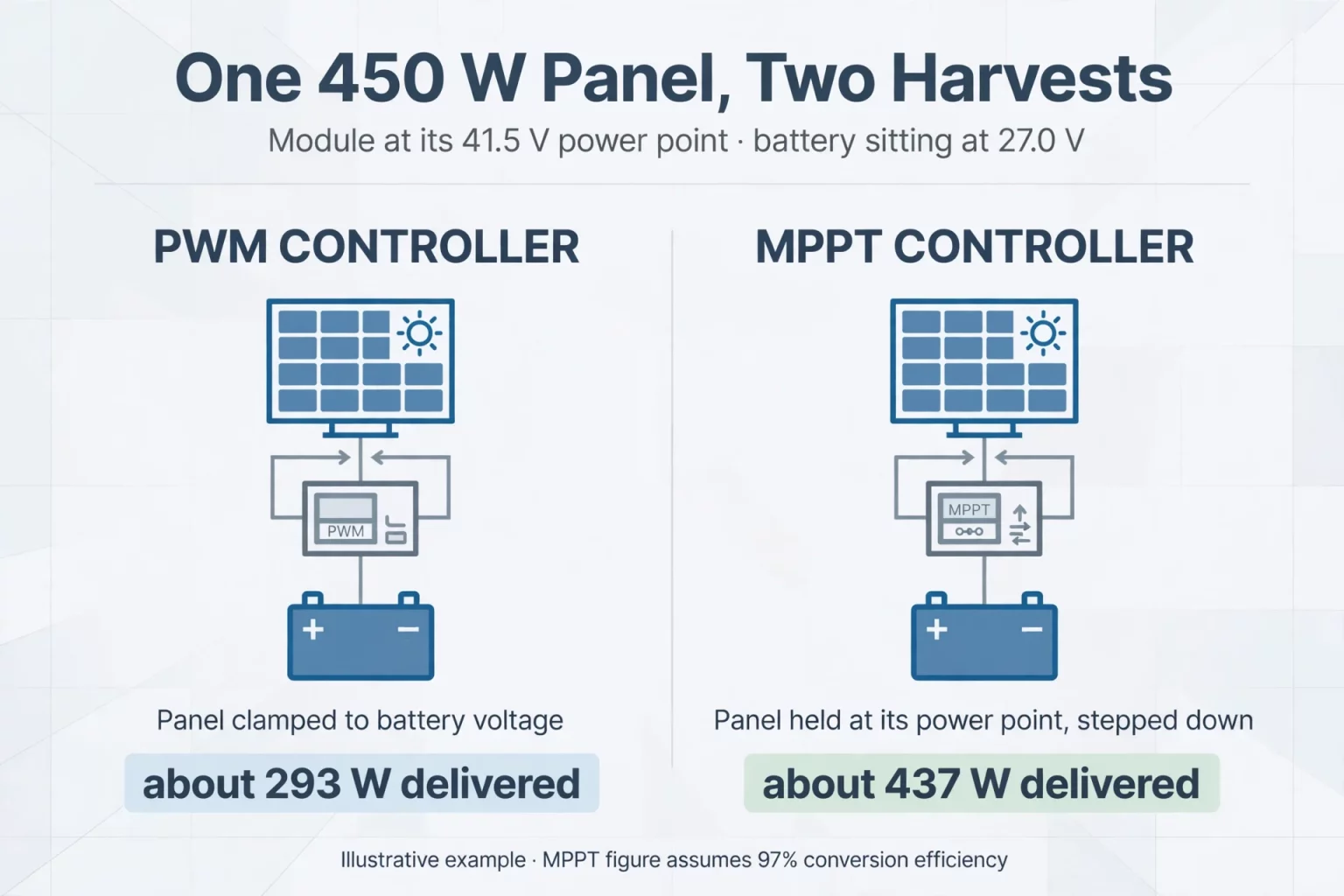
Consider an illustrative 450W module (V_mp = 41.5V, I_mp = 10.85A at STC) charging a 25.6V battery sitting at 27.0V:
- On a PWM controller, the module is clamped near 27.0V, yielding roughly 10.85A × 27.0V ≈ 293W.
- On an MPPT controller, the module operates at 41.5V (450W) and steps voltage down at an assumed 97% conversion efficiency, delivering roughly 437W (16.2A at 27.0V).
Model-Specific CC/CV Charging Profiles and BMS Closed-Loop Control
Lithium storage units charge using a Constant Current / Constant Voltage (CC/CV) sequence governed by the battery's BMS and official specification sheet:
- 1. Constant Current (CC / Bulk Stage): The charger delivers available solar current up to the lower of the inverter's maximum battery current limit (such as 100A on R5KL1DA-G2S-C or 120A on R6KL1DA-G2S-C) and the battery's rated charge current limit (200A max charge current on both MEG-Solid-512314FL1 and MG 512314) until terminal voltage reaches the model's specified charging voltage.
- 2. Constant Voltage (CV / Absorption & Taper Stage): The charger holds terminal voltage at the manufacturer-specified charging setpoint while current tapers down, allowing the BMS balancer to equalize cells:
- — On the MEG-Solid-512314FL1 (51.2V / 314Ah / 16.07 kWh), MegSolid's official specification lists a CC-CV charging voltage of 57.6V (with a 57.6V charging cutoff and 43.2V discharging cutoff).
- — On the MG 512314 (51.2V / 314Ah / 16,076 Wh), the official product table specifies a standard charge condition of 0.5C constant current to 58.4V constant voltage, continuing until current declines to ≤ 0.01C (operating voltage range 40V to 58.4V).
- 3. BMS Self-Adaptation and Float Behavior: Installers must not apply generic third-party absorption or float voltage numbers across different lithium models. Instead, configure the hybrid inverter for closed-loop BMS control (Self-adaption to BMS via the official CAN BMS port on the G2S-C series) or follow the exact voltage parameters in the model's user manual.
Charging Batteries with Solar Power: DC-Coupled vs. AC-Coupled Topologies
When designing a system for charging batteries with solar power, engineers choose between DC-coupled hybrid inverter topologies and AC-coupled retrofit topologies. Table 2 presents a simplified conceptual comparison of the two paths.
Table 2: Simplified Conceptual Comparison of DC-Coupled vs. AC-Coupled Solar Charging
| Engineering Dimension | DC-Coupled Architecture (Hybrid Inverter) | AC-Coupled Architecture (Grid-Tied PV Inverter + Storage Inverter) |
|---|---|---|
| Simplified Conversion Path (PV to Battery) | Direct DC path: PV Array (DC) → MPPT / DC-DC Stage → Battery (DC) | Multi-stage path: PV Array (DC) → Grid PV Inverter (AC) → Bidirectional PCS (DC) → Battery |
| Relative Charging Conversion Loss | Lower conversion loss (avoids intermediate AC inversion during battery charging) | Higher cumulative loss due to additional DC-to-AC-to-DC conversion stages |
| Potential to Harvest Oversized PV Above AC Rating | Capable of routing surplus DC power to battery (subject to DC-bus, PCS & BMS limits) | Clipped at the grid-tied PV inverter’s AC output ceiling before reaching the AC bus |
| Off-Grid Black-Start Behavior | Solar MPPT can wake and charge battery on the DC bus (per inverter firmware rules) | Requires storage inverter to establish a stable AC microgrid reference first |
| Primary Deployment Scenario | New residential and commercial solar-plus-storage installations | Retrofitting battery storage onto sites with existing grid-tied string or micro-inverters |
Engineering Notes on Table 2:
- Hardware-Dependent Conversion Topologies: The stage descriptions in Table 2 represent simplified conceptual paths. In actual power electronics hardware, a DC-coupled hybrid inverter still executes internal DC-DC voltage conversion (such as stepping PV string voltage down or up to the internal DC link and through a bidirectional battery DC-DC stage), so actual charging efficiency depends on the specific inverter's isolation topology, switching frequency, and operating load factor.
- AC Coupling Support on MegSolid Inverters: In MegSolid's official documentation, the G2S-C single-phase energy storage inverter series (3 kW to 6 kW) explicitly lists on-grid and off-grid AC coupling capability. However, specific AC-coupled wiring configurations, maximum connectable PV inverter ratios, and off-grid frequency-shifting curtailment settings must be verified against the G2S-C installation manual before field deployment. For three-phase R30KH3 / R40KH3 / R50KH3 projects requiring AC coupling, contact MegSolid engineering to confirm supported firmware and wiring modes.
How DC-Coupled Hybrid Inverters Handle Oversized PV Arrays
Both the single-phase G2S-C series and the three-phase R30KH3 / R40KH3 / R50KH3 series publish a maximum PV input power rating equal to 1.5× their rated AC output power (for example, 9 kW max PV input on the 6 kW R6KL1DA-G2S-C, and 75 kW max PV input on the 50 kW R50KH3).
Consider an illustrative midday scenario on an R50KH3 (50 kW rated AC output, 55 kW max battery charge/discharge power, 75 kW max PV input) when a 75 kW rooftop array produces 65 kW of available DC power:
- A standalone 50 kW grid-tied PV inverter would cap total conversion at its 50 kW AC limit, clipping the remaining 15 kW of potential array output.
- In a DC-coupled hybrid inverter system, whether part or all of that 15 kW surplus DC power can be directed into the battery while the inverter exports 50 kW AC depends on the inverter's internal DC-bus power allocation limits, total thermal capacity, conversion losses, and the battery BMS's real-time charge acceptance (which requires the battery to be at a state of charge below constant-voltage taper and within its permitted charging temperature window).
Low-Voltage (51.2V) vs. High-Voltage (150V to 800V) Solar Battery Charging
By Ohm's power law (I = P / V), the battery bank's real-time operating voltage directly determines the DC current required to achieve a target charging or discharging power, as well as the maximum power obtainable at a fixed inverter current ceiling.
Special Engineering Focus: How the 120A Current Limit Governs Power on a 6 kW 48V/51.2V Inverter
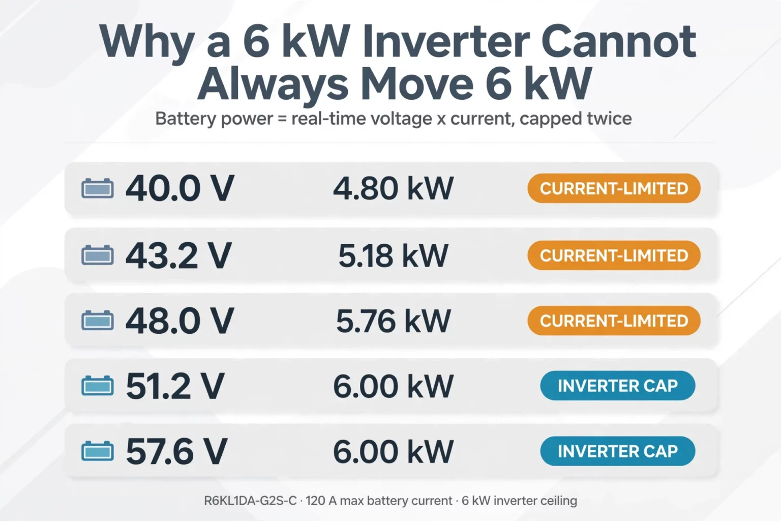
Installers often assume a 6 kW single-phase hybrid inverter (R6KL1DA-G2S-C) can always charge or discharge a 51.2V battery at a full 6.0 kW. In reality, the R6KL1DA-G2S-C has a maximum battery current rating of 120A (and a 6 kW maximum battery charge/discharge power ceiling).
Table 3 shows the theoretical DC power corresponding to the 120A current ceiling across the operating voltage range of a 48V / 51.2V battery bank, alongside high-voltage comparisons on the R50KH3.
Table 3: Real-Time Battery Voltage, Current Limits, and Theoretical DC Power
| Inverter & Current Limit | Real-Time Battery Voltage | Theoretical DC Power (V × I) | Effective Power After Inverter Ceiling & Engineering Implication |
|---|---|---|---|
| R6KL1DA-G2S-C (120A max, 6 kW cap) | 40.0V (lower bound of G2S-C & MG 512314) | 4.80 kW | Current-limited to 4.80 kW DC (120A ceiling reached before 6 kW) |
| R6KL1DA-G2S-C (120A max, 6 kW cap) | 43.2V (MEG-Solid-512314FL1 discharge cutoff) | 5.18 kW | Current-limited to 5.18 kW DC at low SOC |
| R6KL1DA-G2S-C (120A max, 6 kW cap) | 48.0V (G2S-C rated battery voltage) | 5.76 kW | Current-limited to 5.76 kW DC at 48.0V |
| R6KL1DA-G2S-C (120A max, 6 kW cap) | 51.2V (nominal 16S LFP plateau) | 6.14 kW | Capped at 6.00 kW by inverter power limit (~117.2A at 51.2V) |
| R6KL1DA-G2S-C (120A max, 6 kW cap) | 57.6V (MEG-Solid-512314FL1 charge voltage) | 6.91 kW | Capped at 6.00 kW by inverter power limit (~104.2A at 57.6V) |
| R50KH3 (80A × 2 inputs, 55 kW cap) | 400V to 800V HV battery stack | 55.0 kW (137.5A total at 400V; 68.8A total at 800V) | Requires verifying dual-port wiring and current-sharing behavior |
Key Takeaways from Table 3:
- Fundamental Power-Limiting Rule: Actual battery charging and discharging power is limited by the inverter's rated power, maximum battery current, real-time pack voltage, and BMS operating limits. Even on a 6 kW inverter, when low State of Charge causes battery terminal voltage to sag below 50.0V (6,000W / 120A = 50.0V), the 120A current limit restricts actual DC power below 6 kW (down to 5.18 kW at 43.2V or 4.80 kW at 40.0V).
- Low-Voltage Electrical Safety Precautions: Although 51.2V nominal systems operate within a 43.2V to 57.6V (MEG-Solid-512314FL1) or 40V to 58.4V (MG 512314) operating window, nominal voltage is not equal to maximum system voltage, and operating below 60V DC does not eliminate electrical hazards. Because 314Ah lithium units can deliver high fault currents and sustain DC arcs, installers must still provide properly rated DC overcurrent breakers/fuses, insulated terminal covers, and arc-flash clearances.
- Dual Battery Inputs on the R-Series (80A x 2): The R30KH3, R40KH3, and R50KH3 three-phase hybrid inverters feature two battery inputs rated at 80A each (150V to 800V DC). Engineers must not assume that a 55 kW charge/discharge load (137.5A total at 400V) automatically splits 50/50 across the two 80A ports under all operating conditions; whether the two ports operate as independent battery channels or parallel inputs depends on the specific battery rack topology and inverter configuration confirmed with MegSolid.
- Standalone C&I Cabinets vs. R-Series Hybrid Inverters: MegSolid's C&I all-in-one cabinets, such as the ESSA0100B-0215 (672V to 850V DC, which includes its own 100 kW PCS and built-in MPPT PV input up to 1,000V) and the Energon (676V to 936V DC, 125 kVA), integrate their own power conversion stages and exceed the 800V battery upper limit of the R50KH3, so they are deployed as complete C&I systems rather than paired with an R-series hybrid inverter.
4 Engineering Rules for Safe, Long-Life Solar Battery Charging
1. Match the Inverter's Exact BMS Communication Port (CAN on G2S-C)
While MegSolid's MEG-Solid-512314FL1 and MG 512314 units provide RS485, RS232, and CAN communication ports on the battery side, the single-phase G2S-C hybrid inverter series officially specifies CAN as its BMS communication interface (Self-adaption to BMS). Installers pairing a G2S-C inverter with a compatible battery should wire the closed-loop CAN connection (not RS485) and verify protocol compatibility so the BMS can dynamically communicate charge voltage and current limits.
2. Calculate Cold-Morning PV String Open-Circuit Voltage (NEC 690.7)
Solar module open-circuit voltage (V_oc) increases as ambient temperature drops below 25^°C. Using an illustrative 450W module with V_oc,STC = 49.5V and a temperature coefficient of -0.27%/^°C, a -15^°C winter morning (Δ T = 40^°C below STC) increases V_oc by a factor of 1 + (0.0027 × 40) = 1.108:
- Cold-corrected V_oc per module: 49.5V × 1.108 = 54.85V.
- On the single-phase G2S-C series, which has a confirmed maximum PV input voltage of 550V and an MPPT operating window of 100V to 430V, connecting 10 modules in series would reach 548.5V at -15^°C (leaving almost no safety margin below 550V), whereas an 8-module string (396V at STC; 438.8V V_oc at -15^°C; V_mp well inside 100–430V) stays safely within the G2S-C voltage limits.
- For the three-phase R30KH3 / R40KH3 / R50KH3 series, because llms-full.txt does not list the maximum PV input voltage figure, installers must verify the exact maximum PV input voltage and MPPT voltage window on the official R-series product datasheet and equipment nameplate before designing string lengths.
3. Enforce the Official Charging and Discharging Temperature Windows
MegSolid specifies distinct charging and discharging temperature limits for its two 51.2V314Ah residential units:
- MEG-Solid-512314FL1 (51.2V / 314Ah / 16.07 kWh): Charge temperature 0^°C to 45^°C (32^°F to 113^°F); discharge temperature -20^°C to 60^°C (4^°F to 140^°F); storage temperature 0^°C to 45^°C.
- MG 512314 (51.2V / 314Ah / 16,076 Wh): Recommended charging temperature 0^°C to 50^°C; recommended discharging temperature -15^°C to 50^°C; storage temperature -15^°C to 50^°C.
Because charging lithium cells below 0^°C risks metallic lithium plating on the anode, the BMS blocks solar charging whenever cell temperature sits below 0^°C. For installations in freezing climates, locate the battery bank in a temperature-controlled indoor space or consult MegSolid regarding thermal enclosure solutions.
4. Verify Voltage Boundary Differences Between G2S-C, MEG-Solid-512314FL1, and MG 512314
When pairing a 48V / 51.2V battery with the G2S-C single-phase inverter, engineers must check the exact upper voltage boundary of each model:
- G2S-C Single-Phase Inverter Battery Port: Rated 48V, operating range 40V to 58V.
- MEG-Solid-512314FL1 (16.07 kWh): Working voltage range 43.2V to 57.6V, with a standard charging voltage of 57.6V. Its entire operating and charging range sits inside the 40V to 58V window of the G2S-C inverter (subject to confirming CAN BMS protocol compatibility).
- MG 512314 (16,076 Wh): Battery voltage range 40V to 58.4V, with a standard charge condition of 58.4V constant voltage. Because 58.4V exceeds the 58.0V upper limit of the G2S-C battery input port by 0.4V, and because the 57.6V charging setpoint belongs specifically to the MEG-Solid-512314FL1 and cannot be arbitrarily reassigned to the MG 512314, installers must not assume direct plug-and-play charging compatibility between the MG 512314 and G2S-C without first confirming approved BMS charge-voltage limits with MegSolid engineering.
FAQ
Should I choose a DC-coupled or AC-coupled system for solar recharging?
DC coupling is generally preferred for new solar-plus-storage installations because solar DC power charges the battery through the hybrid inverter's internal DC-DC conversion path without first being inverted to AC and rectified back to DC. AC coupling is suited for retrofit projects where a home or facility already has an existing grid-tied PV inverter; MegSolid's G2S-C single-phase inverter supports on-grid and off-grid AC coupling (verify project-specific wiring and control settings in the manual).
What is the difference between the MEG-Solid-512314FL1 and MG 512314 when pairing with a 48V inverter?
The MEG-Solid-512314FL1 (51.2V / 314Ah / 16.07 kWh) operates from 43.2V to 57.6V with a 57.6V CC-CV charging voltage, 200A max charge and continuous discharge current, ≤ 15 mΩ internal impedance, and 0^°C to 45^°C charge / -20^°C to 60^°C discharge temperature windows. The movable MG 512314 (16,076 Wh, parallel up to 6 units, -15^°C to 50^°C discharge) operates from 40V to 58.4V with a 58.4V standard charge voltage; because 58.4V sits above the 58V battery port limit of the G2S-C inverter, MG 512314 inverter pairing and BMS settings must be confirmed with MegSolid before installation.
How do I estimate the PV array size needed to recharge a 51.2V 314Ah battery?
Start with daily battery energy to replace, then divide by the assumed PV-to-battery charging efficiency and the site’s peak sun hours. The source example cycles 12.86 kWh from a 16.07 kWh battery at 80% DoD. At 4.5 peak sun hours and 90% charging efficiency, the calculated array is about 3.17 kW for battery replenishment alone. Add daytime loads and check inverter PV input limits.
What are the practical differences between MPPT and PWM solar charge controllers?
PWM pulls the PV module operating voltage toward battery voltage, leaving some potential module power unused when the two voltages differ significantly. MPPT uses DC-DC conversion to operate near the panel’s maximum power point. In the source’s illustrative 450 W panel example, a PWM controller provides about 293 W at a 27 V battery, compared with about 437 W for an MPPT controller assuming 97% efficiency.
Can the MG 512314 battery connect directly to the G2S-C 48V hybrid inverter?
Direct compatibility must be confirmed by MegSolid. The published MG 512314 charge setting reaches 58.4 V, while the G2S-C battery input window ends at 58.0 V. The MEG-Solid-512314FL1 instead specifies a 57.6 V charging voltage within that inverter window. The installer must also verify the exact BMS communication protocol and approved charger settings; voltage class alone does not establish plug-and-play compatibility.
Why must installers calculate solar string Voc at the lowest site temperature?
A solar module’s open-circuit voltage increases as temperature falls. The source demonstrates that ten example 49.5 V Voc modules could reach approximately 548.5 V at −15°C, almost touching the G2S-C inverter’s 550 V maximum PV input voltage. Check the manufacturer’s voltage-temperature coefficient, the local minimum temperature, the inverter voltage ceiling, and the MPPT operating range before confirming the series string length.
What determines the actual charging power of a 6 kW 51.2V solar inverter?
The inverter rating is only one ceiling. The battery-port current limit, instantaneous battery voltage and BMS charge acceptance also restrict power. The R6KL1DA-G2S-C is rated at 120 A battery current and 6 kW maximum battery power. At 43.2 V, that current corresponds to about 5.18 kW DC; around 51.2 V, the 6 kW inverter ceiling becomes the limiting factor. Conversion and thermal losses remain project-dependent.
What should United States installers verify before sizing PV strings in a cold climate?
Use the site’s design minimum temperature when checking PV string open-circuit voltage, and verify the calculation against applicable electrical code provisions, such as NEC 690.7, and the actual inverter nameplate. The article’s G2S-C example has a 550 V maximum PV input voltage, so a string that appears compliant at 25°C may approach its limit during winter. Confirm BMS charging temperature and wiring protection separately.
What should European homeowners check when charging batteries through a hybrid solar inverter?
Check the exact battery voltage and charging cutoff, inverter MPPT window, approved BMS protocol, and array voltage at the lowest expected temperature. If an existing grid-tied PV system is being retrofitted, evaluate whether AC coupling is supported by the inverter model and firmware. For new systems, compare a DC-coupled architecture. Applicable local electrical and grid requirements must also be checked for the actual installation.
What should South African solar installers verify when selecting a 51.2V battery and inverter?
Confirm the selected battery’s maximum charge voltage, the inverter’s battery input range, supported CAN BMS protocol, PV input and MPPT voltage limits, and the site’s charging temperature conditions. The source distinguishes the MEG-Solid-512314FL1 charge setting of 57.6 V from the MG 512314 setting of 58.4 V. It also shows why battery current and voltage, rather than the inverter nameplate alone, determine available charge power.
Configure Your Solar + Storage System with MegSolid Engineering
Designing a reliable solar recharging system requires aligning PV string cold-weather voltage, inverter battery current limits, and model-specific BMS charging windows. Whether your project calls for a 3 kW to 6 kW single-phase G2S-C inverter, a 30 kW to 50 kW three-phase R30KH3 / R40KH3 / R50KH3 hybrid inverter, or 51.2V314Ah residential storage units, MegSolid provides complete datasheet verification and system matching support.
Contact our engineering team with your daily load profile, PV module datasheet, and site temperature extremes to confirm a verified configuration:
- For 3 kW to 6 kW Single-Phase & 30 kW to 50 kW Three-Phase Hybrid Inverters: Review official MPPT windows, battery current ratings, and AC-coupling capabilities on our Energy Storage Hybrid Inverters page.
- For 51.2V 314Ah Residential Storage Units (MEG-Solid-512314FL1 & MG 512314): Compare voltage windows, cycle ratings, and communication interfaces on our Residential Energy Storage Systems page.