
What is battery c rating in stationary energy storage? Every battery's c-rate (charge and discharge rate) expresses the electric current flowing into or out of the battery relative to its rated Amp-hour (Ah) capacity. Under a nominal 1C rate, the applied current equals the battery's rated Ah figure (for example, 314A for a 314Ah storage cell), corresponding to a theoretical 1-hour full discharge; a 0.5C rate equals half the rated Ah (157A for 314Ah) over a theoretical 2-hour window; and a 0.25C rate equals one-quarter of rated Ah (78.5A for 314Ah) over 4 hours.
For solar installers and plant electrical engineers, matching the continuous and peak battery c rate to your bidirectional Energy Storage Inverters & PCS determines whether a storage bank safely clips factory demand spikes or trips offline on overcurrent and thermal derating. This engineering guide walks through exact C-rate and P-rate formulas, Joule heating physics (I^2R), and hardware sizing across MegSolid's 51.2V residential units and 55.3 kWh to 5,015.9 kWh Commercial & Industrial (C&I) Energy Storage systems.
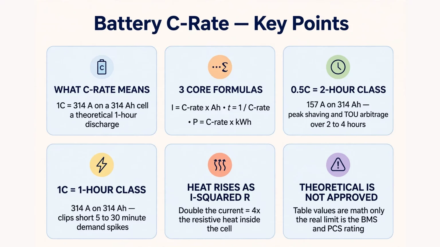
Battery C-Rate Calculation Formula & Reference Lookup Chart
Most consumer articles explain c rating for batteries using small 2,000 mAh drone cells. Stationary BESS engineering applies the same fundamental coulombic ratios to 120Ah, 280Ah, and 314Ah prismatic lithium cells and multi-hundred-volt series strings.
The 3 Core C-Rate and P-Rate Equations
- 1. Calculating DC Current (Amps) from C-Rate and Rated Capacity (Ah):
I (A) = C-Rate (h⁻¹) × C_rated (Ah)
- — Example on a 314Ah Cell (SHS180-314Ah or Energon 1P260S string): Discharging at 0.5C draws 0.5 × 314Ah = 157.0A. Discharging at 0.2C (the standard test rate on the MG 512314 movable unit) draws 0.2 × 314Ah = 62.8A.
- — Example on a 280Ah Cell (ESSA0100B-0215 1P240S string): Discharging at 0.5C draws 0.5 × 280Ah = 140.0A.
- 2. Calculating Theoretical Nominal Duration (Hours) from C-Rate:
t_theoretical (h) = (1) / (C-Rate)
- — Engineering Boundary Note: While 1 ÷ 0.5C = 2.0 hours and 1 ÷ 1.0C = 1.0 hour represent theoretical 100% Depth of Discharge (DoD) durations, actual field discharge duration is shorter because the Battery Management System (BMS) enforces an operating SOC/DoD window (such as 80% to 90% DoD) and cuts off when the weakest cell reaches the lower voltage threshold. During charging, the Constant Voltage (CV) absorption taper stage extends total charging time beyond 1 / C-Rate.
- 3. Estimating Nominal DC Power (kW) and Power-to-Energy Ratio (P-Rate):
P_DC,nom (kW) = (I (A) × V_nom (V)) / (1000) = C-Rate × E_nom (kWh)
- — Engineering Boundary Note: Multiplying C-rate by nominal energy (E_nom) yields theoretical DC power at nominal voltage (3.2V per LFP cell). Actual AC output power at the grid point of coupling depends on real-time string voltage under load, PCS conversion efficiency, auxiliary cooling consumption, and operating power factor (kW = kVA × cosφ).
Table 1 provides an engineering lookup matrix across five C-rates for a typical 100Ah (51.2V) battery, a 280Ah C&I string (ESSA0100B-0215), and a 314Ah cell/string (Energon / MEG-Solid-512314FL1). Theoretical C-rate calculations do not represent the approved continuous power or current limits of the complete BESS.
Table 1: Battery C-Rate Lookup Chart (Current, Theoretical Duration & Nominal DC Power)
| C-Rate (c-rate) | Theoretical Duration (100% DoD) | 100Ah (51.2V) Illustrative Unit | 280Ah Cell / String (ESSA0100B-0215 1P240S, 768V Nom.) | 314Ah Cell / String (Energon 1P260S, 832V Nom.) |
|---|---|---|---|---|
| 0.1C | 10.0 h | 10 A (0.51 kW DC nom.) | 28.0 A (21.50 kW DC nom.) | 31.4 A (26.12 kW DC nom.) |
| 0.2C | 5.0 h | 20 A (1.02 kW DC nom.) | 56.0 A (43.01 kW DC nom.) | 62.8 A (52.25 kW DC nom.) |
| 0.25C | 4.0 h | 25 A (1.28 kW DC nom.) | 70.0 A (53.76 kW DC nom.) | 78.5 A (65.31 kW DC nom.) |
| 0.5C | 2.0 h | 50 A (2.56 kW DC nom.) | 140.0 A (107.52 kW DC nom.) | 157.0 A (130.62 kW DC nom.) |
| 1.0C | 1.0 h | 100 A (5.12 kW DC nom.) | 280.0 A (215.04 kW DC nom., theoretical only) | 314.0 A (261.25 kW DC nom., theoretical only) |
How to Interpret Table 1 Against Official System Ratings:
- Why System AC Ratings Differ from Theoretical 0.5C and 1C DC Figures: In Column 4, the 1.0C (215.04 kW) and 0.5C (107.52 kW) values are purely mathematical DC products of a 280Ah 1P240S string at 768V nominal voltage. In actual hardware, the ESSA0100B-0215 cabinet is officially rated at 0.5C (@ 25^°C) on the battery side and paired with a 100 kW rated AC PCS (100 kW / 215.04 kWh ≈ 0.465 kW/kWh), meaning the 215.04 kW 1C figure is never an approved operating mode for that cabinet.
- Apparent Power (kVA) vs. Theoretical String Power on the Energon Cabinet: In Column 5, the 0.5C (130.62 kW) and 1.0C (261.25 kW) figures represent theoretical string calculations for a 314Ah 1P260S string at 832V nominal. On the official Energon specification sheet, the complete cabinet is rated at 261.24 kWh and 125 kVA AC apparent power (480V / 400V AC), giving an apparent power-to-energy ratio of 125 kVA / 261.24 kWh ≈ 0.478 kVA/kWh (where actual active kW output depends on operating power factor and system limits).
- Maximum Current Limits on 51.2V 314Ah Residential Units: MegSolid's MEG-Solid-512314FL1 (51.2V / 314Ah / 16.07 kWh) specifies a maximum charge current of 200A and a maximum continuous discharge current of 200A. Dividing 200A by 314Ah equals a 0.637C continuous current capability (10.24 kW theoretical DC power at 51.2V nominal).
0.5C vs. 1C C Rate Battery Systems: How to Select Your C&I BESS Architecture
When EPC contractors review commercial energy storage tenders, systems are typically grouped by their official C-rate specification or their power-to-energy ratio into 0.5C (2-hour class) and 1C (1-hour class) configurations. Within MegSolid's ESSA outdoor cabinet lineup, both 0.5C and 1C models are offered to match distinct industrial load profiles.
1. Why 0.5C (2-Hour Class) Fits Daily Peak Shaving and TOU Arbitrage
In MegSolid's C&I portfolio, the ESSA0050B-0100 (50 kW / 100.352 kWh) and ESSA0100B-0215 (100 kW / 215.04 kWh) carry an official 0.5C (@ 25^°C) rating using 3.2V / 280Ah LFP cells (≥ 5,000 cycles), while the air-cooled container series ESSC0500B-1075 (500 kW / 1.0752 MWh) and ESSC1000B-2150 (1,000 kW / 2.1504 MWh) operate at an equivalent ~2-hour power-to-energy ratio (0.465 kW/kWh):
- Aligning with 2-to-4-Hour Commercial Peak Tariff Windows: Utility Time-of-Use (TOU) peak price windows and factory afternoon demand plateaus commonly span 2 to 4 hours. Operating a 2-hour class cabinet allows the plant EMS to discharge across a 2-hour peak window (or modulate at 0.25C to 0.33C across 3 to 4 hours) without paying for oversized PCS inverter capacity that sits idle during multi-hour dispatch.
- Cell Model Selection and Cycle Life Specifications: Within the ESSA outdoor cabinet table, the 0.5C models (ESSA0050B-0100 and ESSA0100B-0215, built with 3.2V / 280Ah LFP cells) list a cycle rating of ≥ 5,000 cycles, whereas the 1C models (ESSA0030B-0055 and ESSA0050B-0055, built with 3.2V / 120Ah / 1C LFP cells) list ≥ 3,800 cycles. Because these cabinets use different cell models, capacities, and test conditions, the cycle life figures reflect the combined cell specification and test protocol rather than C-rate alone, though operating any given cell at lower currents reduces thermal and electrochemical stress.
2. When Industrial Sites Require a 1C (1-Hour Class) C Rate Battery System
When a facility experiences steep, short-duration power spikes rather than multi-hour plateaus, sizing the battery for a 2-hour rate forces the buyer to purchase twice the kilowatt-hour capacity only to obtain the needed kilowatt output. A 1C c rate battery configuration addresses three specific industrial duties:
- Short-Duration High-Inrush Peak Clipping: Metal stamping lines, sawmill headrigs, and injection molding banks generate sharp 5-to-30-minute demand spikes that trigger monthly utility peak-demand charges. In MegSolid's ESSA0050B-0055 cabinet (1,770 × 1,510 × 2,270 mm), a 55.296 kWh (1P144S, 460.8V nominal) battery bank built from 3.2V / 120Ah / 1C LFP cells (with an official 1C @ 25^°C battery charge/discharge specification) is paired with a 50 kW rated AC PCS (0.904 kW/kWh AC-to-DC ratio), while the ESSA0030B-0055 pairs the same 55.296 kWh 1C-rated battery bank with a 30 kW rated AC PCS.
- Generator Spinning-Reserve Bridge: During a grid outage or generator transition, a high-rate BESS can support critical plant loads during the bridge window required for standby diesel generators to start, stabilize, synchronize, and accept load steps according to site-specific generator control timelines.
- Grid Frequency Regulation (1P Duty): On MegSolid's standalone SHS180-314Ah hybrid solid-liquid cell specification sheet (which requires verification of the original cell datasheet and batch test reports per contract), the cell is rated for 6,000 cycles to ≥ 80% SOH at 0.5P/0.5P (100% DoD) and explicitly supports 1P frequency regulation duty. At the utility scale, the 5000INTL liquid-cooled container pairs 5,015.9 kWh (12P416S SHS180-314 configuration) with 2,700 kW (450 kW × 6) of AC power (0.538 kW/kWh ratio).
How High C Rates Impact Battery Temperature, Efficiency & Lifespan (Joule's Law Physics)
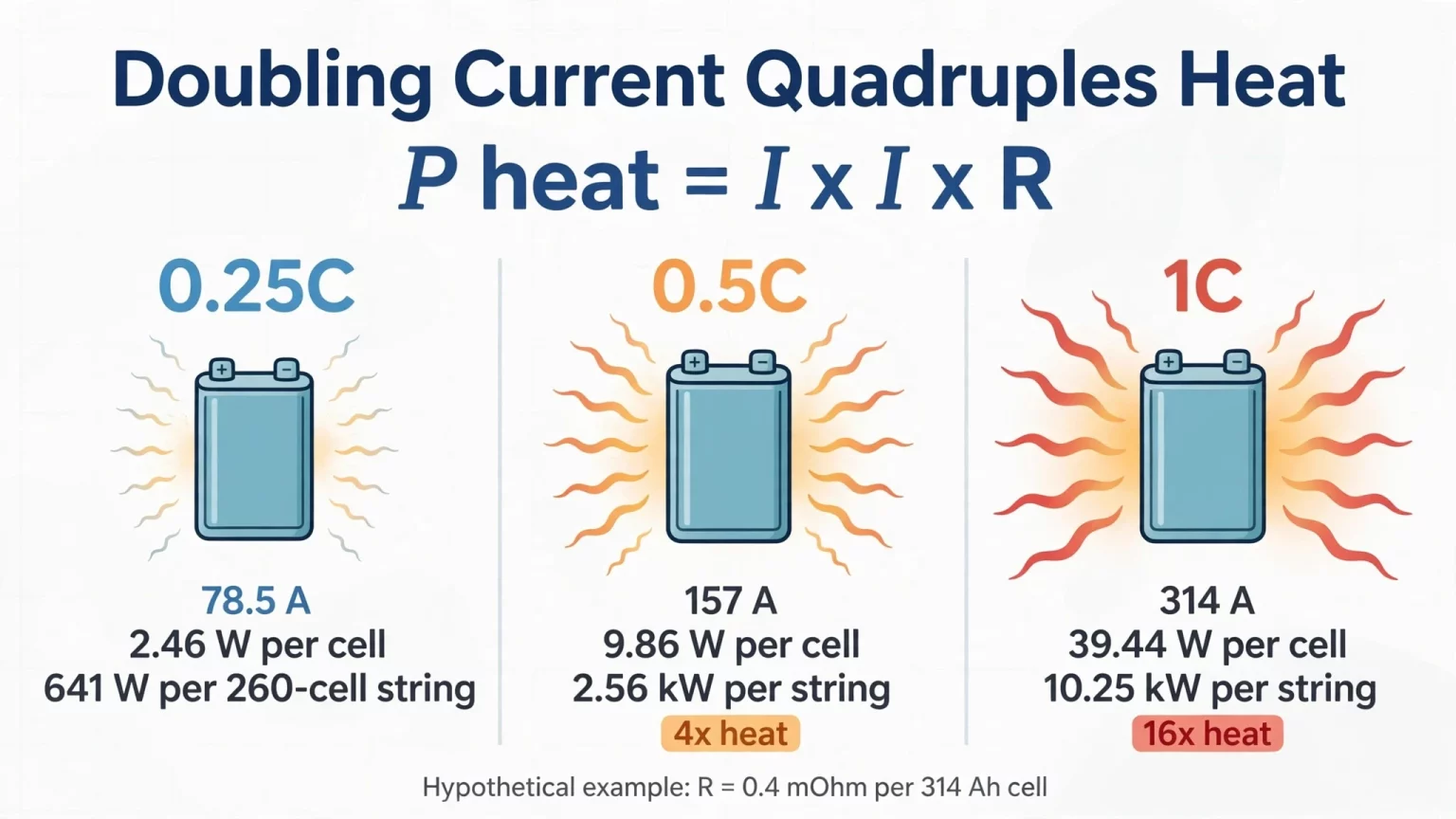
Resistive heating increases with the square of current under constant-resistance conditions. Doubling the current results in approximately four times the resistive heat generation.
Why Doubling the C-Rate Quadruples Internal Joule Heating (P_heat = I^2 R)
Inside every lithium cell and module busbar, instantaneous resistive heat dissipation (P_heat) is proportional to the square of the current multiplied by internal DC resistance (R_DC):
P_heat (W) = I^2 × R_DC
As a hypothetical 260-cell string calculation example based on a 314Ah cell with a DC internal resistance of R_DC = 0.4 mΩ (0.0004 Ω, as listed on the standalone SHS180-314Ah cell specification sheet; note that actual cell impedance inside an Energon 1P260S cabinet must be confirmed against its specific bill of materials before thermal modeling):
- At 0.25C (78.5A): Single-cell resistive heating is (78.5A)^2 × 0.0004 Ω = 2.46 W per cell (or 641 W across a hypothetical 260-cell series string, before interconnect resistance).
- At 0.5C (157.0A): Current doubles (2 ×), so resistive heating quadruples (2^2 = 4 ×) to (157.0A)^2 × 0.0004 Ω = 9.86 W per cell (2.56 kW across 260 cells).
- At 1.0C (314.0A): Current doubles again (4 × the 0.25C current), causing resistive heating to jump 16 × above the 0.25C baseline to (314.0A)^2 × 0.0004 Ω = 39.44 W per cell (10.25 kW of cell-level heat across a hypothetical 260-cell string!).
Managing High-Rate Thermal Loads: Cell Impedance and Cooling Architecture
The I^2R relationship explains why thermal management and cell impedance must be engineered together when operating at 0.5C to 1C:
- 1. Lowering R_internal at the Cell and Pack Level: On the standalone SHS180-314Ah cell specification sheet, AC resistance is 0.18 ± 0.03 mΩ and DC resistance is 0.4 ± 0.1 mΩ, supporting ≥ 94.5% cell energy efficiency at 0.5P. On the 51.2V 314Ah MEG-Solid-512314FL1 residential unit, internal impedance is maintained at ≤ 15 mΩ (and ≤ 80 mΩ assemblage impedance on the MG 512314 product specification table).
- 2. Matching Air Cooling vs. Liquid Cooling to Ambient Temperature Windows:
- — MegSolid's ESSA outdoor C&I cabinets (55.296 kWh at 1C to 215.04 kWh at 0.5C) use intelligent air cooling within an official operating temperature range of 0^°C to +45^°C (IP54).
- — For wider ambient temperature extremes or dense multi-megawatt blocks, the Energon (261.24 kWh / 125 kVA) C&I cabinet uses intelligent liquid cooling (designed for a 1^°C to 3^°C cell temperature gradient under specified operating conditions, subject to project technical confirmation) across an operating window of -20^°C to +55^°C (with output derating above 45^°C), while the 5000INTL (5,015.9 kWh / 2,700 kW) container uses smart liquid cooling from -30^°C to +55^°C (IP55). Engineers sizing systems for hot industrial yards above 45^°C must factor in the specified high-temperature derating curve during peak afternoon dispatch.
C-Rate vs. P-Rate: The End-of-Discharge Current Escalation Trap in C&I BESS
Low-voltage batteries are typically rated by Constant Current (C-rate, in Amps), whereas commercial and utility BESS cabinets are dispatched by Constant Power (P-rate, in kilowatts). Ignoring the difference between C-rate and P-rate creates a critical sizing error near the bottom of the discharge curve.
When a plant Energy Management System (EMS) commands a PCS inverter to hold a constant active power output (P), the DC current drawn from the battery string is governed by I_DC = P_DC / V_string. As the battery discharges from full charge toward its lower BMS cutoff voltage, string voltage drops, forcing DC current to rise progressively to maintain constant power.
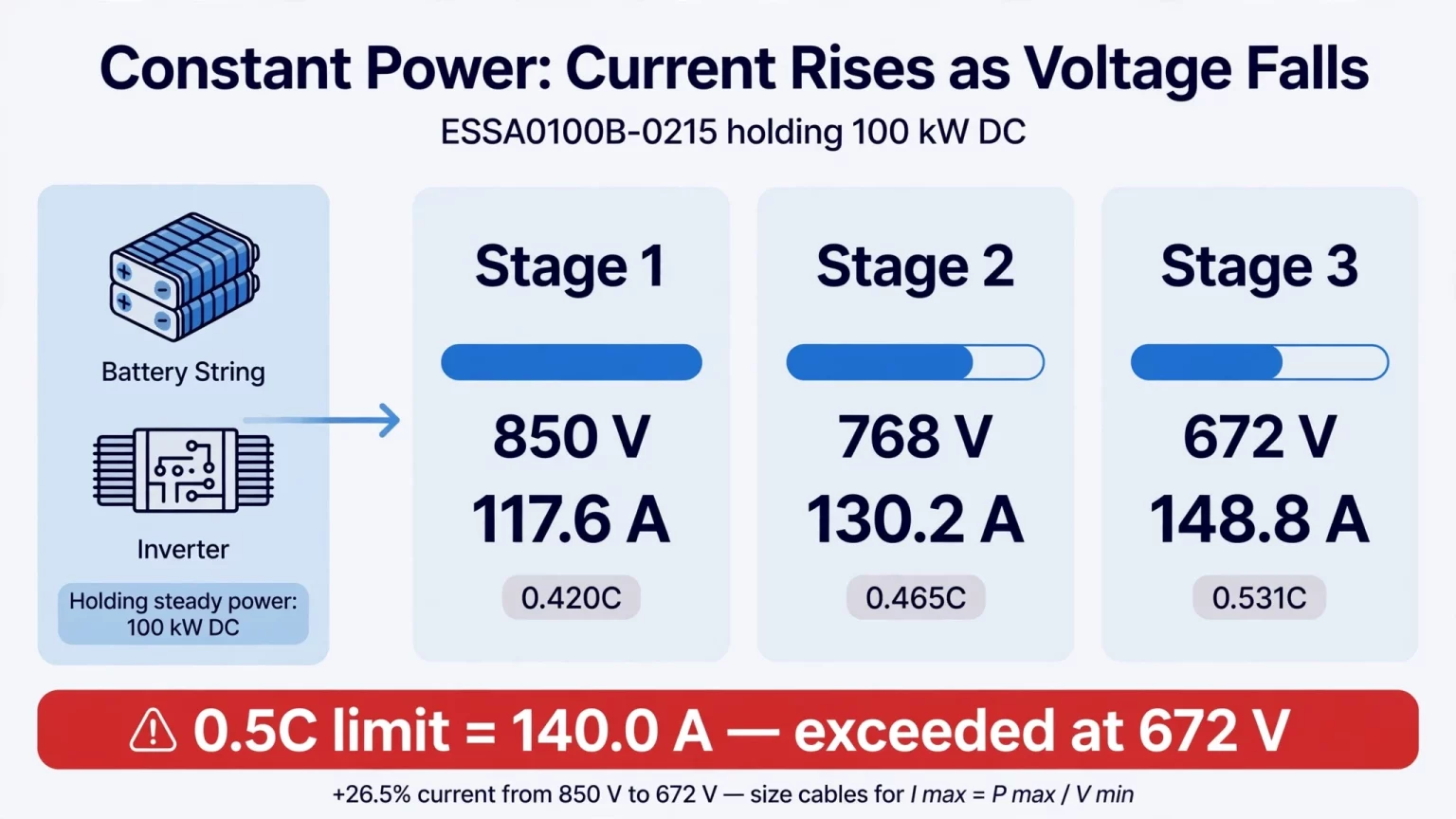
Consider the operating voltage windows of two MegSolid C&I platforms:
- Example 1: ESSA0100B-0215 (100 kW / 215.04 kWh, 1P240S 280Ah, 768V nominal, 672V to 850V DC range):
- — To supply an illustrative 100 kW DC load at the upper voltage limit (850V), the string supplies 100,000W ÷ 850V = 117.6A (0.420C).
- — At nominal voltage (768V), current is 100,000W ÷ 768V = 130.2A (0.465C).
- — Near the lower operating boundary (672V), maintaining 100 kW DC requires 100,000W ÷ 672V = 148.8A (0.531C), representing a 26.5% current increase compared to the 850V start of discharge.
- — Critical Engineering Boundary on ESSA0100B-0215: Because the 280Ah battery string is officially rated at 0.5C (140.0A), a 148.8A (0.531C) DC draw at 672V already exceeds 0.5C, and delivering 100 kW AC at the inverter terminals requires even higher DC input power and current to cover PCS conversion losses. Consequently, if 0.5C (140.0A) is enforced by the BMS as the continuous current limit, the cabinet cannot sustain a full 100 kW output down to the 672V lower boundary. Full-power output across the voltage window is always bounded by the battery continuous current limit and the PCS low-voltage derating curve; engineers must never assume constant 100 kW AC delivery across the entire 672V to 850V span.
- Example 2: Energon (261.24 kWh / 125 kVA, 1P260S 314Ah, 832V nominal, 676V to 936V DC range):
- — Note that Energon is officially rated at 125 kVA apparent power rather than 125 kW active power. Using an illustrative 125 kW DC power draw purely as a mathematical example, string current rises from 133.5A (0.425C) at 936V, to 150.2A (0.478C) at 832V nominal, up to 184.9A (0.589C) at 676V, representing a 38.5% increase across the voltage window. Actual maximum active power and low-voltage current draw remain governed by the operating power factor, conversion losses, BMS current limits, and PCS derating curves.
Consequently, DC cables, fuses, contactors, and PCS DC input current ratings must always be sized for the maximum current at the minimum operating DC voltage (I_max = P_max,DC / V_min,DC), while respecting BMS continuous current limits and low-voltage power derating curves.
Matching Battery C-Rate to MegSolid Hybrid Inverters & Modular PCS
Whether you are integrating a 48V/51.2V residential system or selecting an external commercial PCS, actual charge and discharge power is bounded by four simultaneous limits: inverter rated power, inverter maximum DC current, real-time battery voltage, and BMS current/temperature limits.
Table 2 summarizes official C-rate, current, and power specifications across MegSolid's storage and inverter product lines.
Table 2: MegSolid Battery, Hybrid Inverter & PCS C-Rate Reference Matrix
| MegSolid Product / Series | Official Voltage Window | Official Current / C-Rate Specification | Rated Power / Energy | Integration & C-Rate Sizing Note |
|---|---|---|---|---|
| MEG-Solid-512314FL1 (51.2V Residential) | 43.2V to 57.6V (51.2V nom.) | 200A max charge & continuous discharge (~0.64C on 314Ah) | 16.07 kWh (314Ah) | Voltage overlaps G2S-C 40–58V range (60–120A = 0.19C–0.38C); verify BMS protocol & charge/discharge limits |
| MG 512314 (Movable Residential Unit) | 40.0V to 58.4V | 0.5C (157A) standard charge to 58.4V (product page); 200A max charge/discharge | 16,076 Wh (≥ 314Ah @ 0.2C) | Parallel up to 6 units; confirm BMS & 58.4V upper limit before inverter pairing |
| ESSA0030B-0055 & ESSA0050B-0055 Cabinets | 403.2V to 511.2V (460.8V 1P144S) | Official 1C (@ 25^°C) max charge/discharge rate (120Ah LFP) | 30 kW or 50 kW AC / 55.296 kWh | All-in-one air-cooled C&I cabinet (≥ 3,800 cycles, 0^°C to +45^°C) |
| ESSA0050B-0100 & ESSA0100B-0215 Cabinets | 319.2–397.6V (1P112S) / 672–850V (1P240S) | Official 0.5C (@ 25^°C) max charge/discharge rate (280Ah LFP) | 50 kW / 100.35 kWh & 100 kW / 215.04 kWh | All-in-one air-cooled C&I cabinet (≥ 5,000 cycles, built-in transformer) |
| Energon Liquid-Cooled C&I Cabinet | 676V to 936V DC (832V 1P260S) | 125 kVA AC / 261.24 kWh (~0.478 kVA/kWh power-to-energy ratio) | 125 kVA / 261.24 kWh (314Ah cell) | Liquid-cooled IP54 cabinet (-20^°C to +55^°C, derates >45^°C; up to 10 units) |
| PMA080 / PMA0105 / PMA0125 Modular PCS | 615–950 Vdc (3W+PE) / 650–950 Vdc (3W+N+PE) | ± 150A / ± 195A / ± 230A max DC current | 80 / 105 / 125 kW AC (96 / 126 / 150 kW max DC) | Rack-mount modular PCS (98.7% max efficiency, <20 ms charge/discharge switch) |
| MEGA0030TS to MEGA0500TS Cabinet PCS | 250–850V (30 kW) up to 500–850V (500 kW) | 43A to 722A rated AC current (verify parallel config per project documentation) | 30 / 50 / 100 / 150 / 250 / 500 kW AC | C&I PCS with built-in isolation transformer (96.3% to 97.5% max efficiency) |
Engineering Notes on Inverter and PCS Pairing:
- Residential Single-Phase Pairing (G2S-C Series): On a single MEG-Solid-512314FL1 (314Ah), the 43.2V to 57.6V battery voltage window lies within the 40V to 58V battery port range of the G2S-C inverter series, though engineers must still verify CAN BMS communication protocol compatibility and charge/discharge current and cutoff limits prior to commissioning. Pairing with a 6 kW R6KL1DA-G2S-C inverter (120A max battery current) operates a single 314Ah unit at a conservative 120A ÷ 314Ah = 0.382C maximum rate, below its 200A (0.637C) continuous rating. When battery voltage drops below 50.0V at low SOC, the 120A inverter current limit caps DC power below 6.0 kW (for example, 43.2V × 120A = 5.18 kW).
- Three-Phase High-Voltage Hybrid Inverter Pairing (R30KH3 / R40KH3 / R50KH3): These 30 kW, 40 kW, and 50 kW hybrid inverters (33 / 44 / 55 kW max battery charge/discharge power) accept 150V to 800V DC across two battery inputs rated at 80A each (80A × 2). When pairing with a compatible high-voltage battery stack, verify the battery's continuous C-rate and confirm with MegSolid how current is distributed across the two 80A inputs.
- External C&I PCS Sizing (PMA and MEGA-TS Series): When pairing C&I battery racks with PMA080 / 0105 / 0125 (615–950 Vdc for 3W+PE or 650–950 Vdc for 3W+N+PE, ± 150A to ± 230A max DC current, 98.7% max efficiency) or MEGA0030TS–MEGA0500TS (250–850 Vdc), verify the minimum full-load DC voltage against the controlled PCS datasheet (do not rely on web table formatting for the full-load minimum DC voltage row on the PMA page) so that the battery string's end-of-discharge voltage does not trigger unexpected low-voltage power clipping.
FAQ
How does temperature affect a battery's usable C-rate?
At cold temperatures below 0^°C, charging is blocked by the BMS to prevent lithium plating, while cold discharging experiences higher internal resistance and voltage sag. At elevated ambient temperatures above 45^°C, C&I systems and inverters apply thermal power derating to keep cell and power-electronics temperatures within safe limits (for example, the ESSA series operates from 0^°C to +45^°C, while the liquid-cooled Energon cabinet operates from -20^°C to +55^°C and the PMA PCS operates from -30^°C to +60^°C, both derating above 45^°C).
What is the difference between C-rate and P-rate in BESS datasheets?
C-rate defines a Constant Current (Amps) relative to rated Ah capacity (I = C-rate × Ah), whereas P-rate defines Constant Power (Watts or kilowatts) relative to rated energy (Wh or kWh). In a constant-power discharge (0.5P or 1P), DC current does not remain constant; as battery string voltage declines from full to empty, the PCS draws progressively higher DC current (I = P / V) to hold kilowatt output steady.
How do you calculate the continuous DC current allowed by a battery C-rate?
Multiply the verified maximum continuous C-rate by the battery Ah rating. For a 280 Ah ESSA0100B-0215 string, 0.5C equals 140 A. Then compare that value with the PCS current demand at the lowest operating DC voltage and apply BMS and temperature limits.
Can a 100 kW ESSA0100B-0215 cabinet deliver full power at 672 V?
At 672 V, 100 kW DC requires about 148.8 A, or 0.531C on a 280 Ah string. That exceeds a strict 0.5C/140 A continuous limit before conversion losses. Whether the cabinet can deliver 100 kW AC at low voltage must be checked against its BMS current limit and PCS derating curve.
Is 125 kVA on the Energon cabinet the same as 125 kW?
No. Energon is specified at 125 kVA apparent power, whereas active output in kW depends on power factor and operating limits. For example, at 0.90 power factor, 125 kVA corresponds to 112.5 kW before any other applicable limits.
Why does battery heating increase so sharply at a higher C-rate?
Resistive heat follows P = I² × R when resistance is held constant. Doubling current from 0.25C to 0.5C creates four times the resistive heat; increasing it fourfold to 1C creates sixteen times the original heat. Cell resistance, cooling and busbar design must be verified for the actual duty.
What documents should EPC teams request to validate C-rate and PCS sizing?
Request the model-specific battery and PCS datasheets, continuous and peak current limits, voltage operating window, current-versus-temperature derating curves, discharge energy curves, BMS protocol and protection settings, system single-line diagram, and factory test results. Verify continuous performance at minimum battery voltage.
What should US industrial buyers check before selecting 0.5C versus 1C BESS?
Check the local demand-charge tariff and actual 15-minute facility load profile. Use a 0.5C/two-hour-class configuration when demand peaks are sustained, and evaluate a 1C option for brief high-power surges. Confirm utility interconnection and project-specific safety requirements independently of the theoretical C-rate.
How should German commercial and industrial sites compare battery C-rates?
Use site interval data to separate short demand peaks from sustained multi-hour energy shifting. Compare the PCS active-power requirement with the usable energy target, cell continuous current rating and low-voltage derating. Verify the relevant local grid-connection and installation requirements for the selected system.
How should South African factories choose a BESS C-rate for peak demand and diesel backup?
Review the facility demand profile, tariff peak windows, generator start and transfer sequence, and the duration of critical loads. A two-hour-class cabinet can support sustained dispatch, while a 1C-rated design may suit shorter power spikes. Check BMS limits, minimum DC voltage, PCS transfer architecture and site-specific integration requirements.
Size Your 0.5C or 1C Storage System & PCS with MegSolid
Selecting the right battery c rating and inverter power ratio protects both your project CAPEX and multi-year cell cycle life. Whether your facility requires a 0.5C or 1C ESSA outdoor cabinet (55.296 kWh to 215.04 kWh), a 261.24 kWh / 125 kVA liquid-cooled Energon cabinet, a 5,015.9 kWh / 2,700 kW 5000INTL utility container, or modular PMA and MEGA-TS power conversion systems (30 kW to 500 kW), MegSolid provides verified technical specifications and load-profile sizing support.
Contact our engineering team with your 15-minute utility demand log or site single-line diagram to receive a matched battery and PCS proposal:
- For 3kW–50kW Hybrid Inverters & 30kW–500kW Modular/Cabinet PCS: Compare DC voltage windows, current ratings, and switching specs on our Energy Storage Inverters & PCS page.
- For 0.5C & 1C C&I Outdoor Cabinets & Utility Containers (55kWh to 5MWh+): Explore full specifications and request an engineering audit on our Commercial & Industrial (C&I) Energy Storage page.