 Skip to content
I. Decoding the Underlying Logic of Inverter Topology
Conventional Grid-Tied Inverter: The Baseline for Unidirectional Power Transfer
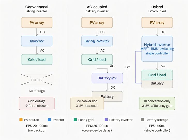
The core task of a conventional grid-tied inverter (String Inverter) is singular: convert direct current (DC) generated by PV modules into alternating current (AC) and feed it into the grid.
The architectural logic is clean, but it has one hard constraint — the Anti-Islanding protection mechanism. When grid voltage is lost, the inverter must shut down within milliseconds to prevent back-feeding power onto a de-energized line, which would pose a safety risk to personnel.
This means: grid outage equals system shutdown, regardless of how much the PV array is producing at that moment.
The power flow is linear: PV → Inverter → Grid/Load. There is no capacity for energy storage integration, no room for peak shaving, and the architectural ceiling is locked in from the moment of design.
Battery Inverter (AC-Coupled): The Bridge for Retrofitting Existing Systems
The AC-coupled approach connects a standalone battery inverter to the AC side of an existing PV system, and is the most common path for retrofit projects.
The actual power flow is: PV → Grid-Tied Inverter (DC-AC) → Battery Inverter (AC-DC) → Battery. On discharge, the path reverses, and the battery goes through one more DC-AC conversion to supply the load.
Every AC-DC or DC-AC conversion introduces an energy loss of 3%–8%. When PV output needs to simultaneously charge the battery, the conversion losses across the two-stage chain are a physical fact that cannot be bypassed.
Cross-device communication is equally a real engineering constraint. Commands are exchanged between the two devices via RS485, CAN, or Modbus, with frame cycles typically in the range of 50ms–200ms. During grid frequency disturbances or sudden load changes, this delay translates directly into latency in power dispatch.
Hybrid Inverter (DC-Coupled): The "Single-Brain" Energy Hub
A hybrid inverter integrates MPPT control, battery charge/discharge management, and on-grid/off-grid switching into a single cabinet. PV DC power charges the battery directly, without any additional AC-DC conversion.
Power flow: PV (DC) → Hybrid Inverter internal DC bus → Battery (direct DC charge) / Load (DC-AC).
The architectural advantages are quantifiable:
- One DC-AC-DC conversion stage eliminated, charging efficiency improved by 3%–8% (depending on power class)
- MPPT and SOC management share the same controller clock, command latency reduced to the microsecond range
- Fewer cables, reduced installation labor, fewer high-voltage DC connection points, and proportionally lower risk of contact faults
Taking the MegSolid R50KH3 three-phase hybrid inverter as an example: a single unit supports 4-channel independent MPPT tracking, maximum PV input power of 75 kW, rated AC output of 50 kW, and a battery voltage compatibility range of 150–800 V. The R50KH3 supports a documented 150–800 V battery-voltage range. The proposed battery must be verified against its complete operating-voltage range, BMS communication requirements and required power before final system selection.
II. Three Core Dimensions That Determine System Engineering Stability
Emergency Power Supply (EPS) Switchover Response Mechanism
Off-grid switchover speed is what industrial users actually care about — not rated power figures.
In a conventional setup (grid-tied inverter + UPS + battery inverter in series), the switchover path involves multiple devices responding sequentially, with typical switchover times of 20ms–100ms, and some configurations even longer. Within this range, voltage-sensitive precision equipment — variable frequency drives, servo systems, precision sensors — may trigger over/under-voltage protection and restart.
The MegSolid R50KH3's specified backup switchover time is <10ms. This comes from its single-controller architecture: a grid voltage-loss signal directly triggers the internal relay action, without waiting for a cross-device communication handshake to complete.
|
Solution Type |
EPS Switchover Time |
Key Impact |
|---|---|---|
| Grid-tied inverter + external UPS | 20ms–100ms | Precision equipment may trigger restart |
| Hybrid inverter (single unit) | <10ms (R50KH3 spec) | Sensitive loads do not perceive the switchover |
Consistency Protection in Battery Dispatch Logic
A battery's real-world lifespan depends on the quality of charge/discharge execution, not just the rated cycle count.
When the MPPT controller and the battery BMS belong to two separate devices, each makes its judgment about the "current optimal charging current" based on its own data — one reads PV-side power, the other reads battery-side SOC — and there is a time-window discrepancy between communication frames. Under fluctuating irradiance conditions, this discrepancy causes "command jitter" in the charging current, which accumulates at the cell level as micro-cycle degradation.
A single-controller architecture eliminates this problem at the root: MPPT output power and battery SOC are read within the same control cycle, and charge commands are generated from a consistent data snapshot.
The MegSolid solid-state cell (314Ah LFP) has a rated cycle life of 8,000 cycles (80% DOD) per its specification sheet. Achieving this figure depends on precise charge/discharge management. Pairing with a hybrid inverter that communicates natively is the engineering assurance that keeps real-world lifespan close to the nameplate value.
Data Aggregation Capability of the Monitoring Architecture
Fault diagnosis efficiency during the O&M phase is determined at system design time.
The monitoring reality of a multi-brand patchwork setup: PV-side data lives on the string inverter's cloud platform; battery-side data lives in the BMS management software. Their timestamps are not necessarily synchronized and their data formats are typically incompatible. Investigating a single event — "why didn't the battery discharge at peak time as expected?" — may require cross-referencing logs from two separate systems and manually reconciling timestamp discrepancies.
A native closed-loop monitoring platform consolidates all data — PV generation, grid interaction power, battery SOC/SOH, temperature curves — into a single data stream. Fault localization shifts from "cross-referencing multi-system logs" to "single-system time-series tracing."
MegSolid energy storage systems support RS485 / CAN / RS232 multi-protocol communication, and the AI early warning system monitors temperature differentials in real time to within ±5°C accuracy. Anomalies can be identified before they cause damage.
III. Selection Decision Tree: Matching Strategy by Project Phase
New-Build PV-Storage Integrated Projects
New-build projects carry no compatibility burden from existing equipment, offering the highest degree of selection freedom and representing the scenario where the hybrid solution's advantages are most fully realized.
Cost structure comparison (equivalent capacity scale, new-build scenario):
|
Cost Item |
Conventional Solution (String Inverter + Battery Inverter) |
Hybrid Inverter Solution |
|---|---|---|
| Equipment procurement | Two inverters purchased separately | Single-unit purchase, one fewer device |
| DC distribution cabinet | DC distribution cabinet | Requires a separate DC distribution panel |
| Installation labor | Two devices installed and commissioned separately | Single-unit installation, fewer wiring points |
| Communication setup | Requires cross-device protocol integration | Native protocol, zero configuration |
| Long-term maintenance | Two suppliers, fault liability split | Single point of responsibility |
In the 30kW–50kW C&I power range, the MegSolid R30KH3 to R50KH3 series covers the mainstream requirements of new-build projects, with maximum PV input capacity of 45–75 kW, a documented 150–800 V battery-voltage range, compatible with MegSolid hybrid solid-state batteries and standard lithium-ion batteries when the proposed battery configuration is verified for the project.
Expansion and Upgrade of Existing PV Systems
The decision logic for retrofitting existing installations differs from new builds. The key question is: the relationship between the remaining service life of the existing grid-tied inverter and the cost of retrofitting.
If the existing string inverter has a remaining service life of >5 years and its power rating still meets the current PV installation, adding a battery inverter (AC-coupled) is the more economically rational path. The engineering trade-offs must be confirmed in advance:
- Efficiency loss: One additional AC-DC conversion stage in the charging path; measured losses of 3%–8%
- Switchover time: EPS response is slower than a native hybrid solution; confirm the load's tolerance range
- Communication compatibility: Verify whether the existing inverter's communication protocol is compatible with the battery inverter, to avoid data silos
- Capacity ceiling: AC-coupled charging power is constrained by the existing inverter's rated output, which may prevent the full battery capacity from being utilized
If the existing inverter is approaching end of life, or the user has a firm EPS switchover time requirement (e.g., <10ms), replacing the entire system with a hybrid solution typically delivers superior long-term economics compared to patching.
IV. MegSolid Hybrid Solid-State Solution: Application of Next-Generation Storage Inverter Technology
Native Communication Integration Between Solid-State Storage and Hybrid Inverter
The thermal runaway mechanism in conventional liquid-electrolyte lithium batteries is fundamentally a chain decomposition reaction of the electrolyte triggered by overcharge, short circuit, or high temperature. The BMS is a passive intervener in this process: it issues protection commands upon detecting temperature or voltage anomalies, but the speed of chemical reactions typically outpaces command response.
MegSolid's Hybrid Solid-State technology cuts this chain at the material level — solid electrolytes have no liquid decomposition pathway, so the chemical trigger conditions for thermal runaway are physically eliminated, rather than relying on BMS software protection as a safety net.
The connection point between this characteristic and the hybrid inverter is: when the cell itself has no thermal runaway pathway, charge/discharge strategies can pursue efficiency more aggressively without reserving excessive protective margins.
Key parameters of the MegSolid 314Ah solid-state cell:
|
Parameter |
Value |
|---|---|
| Nominal Capacity | 314Ah |
| Cycle Life | 8,000 cycles (80% DOD) |
| Internal Resistance | ≤15 mΩ |
| Discharge Temperature Range | -20°C ~ 60°C |
| Charge Temperature Range | 0°C ~ 45°C |
| Monthly Self-Discharge Rate | ≤2% (25°C, 50% SOC) |
The MegSolid Hybrid Solid-State C&I Energy Storage System (261.24 kWh configuration) connects directly to the hybrid inverter via RS485 / CAN. The AI early warning system maintains intra-pack temperature differentials within ±5°C, and BMS data is reported directly to the inverter control layer with no intermediate gateway translation required.
High-Availability Output Performance Under Extreme Conditions
Performance numbers under standard conditions (25°C, rated power) have limited practical relevance for industrial users. The real selection filter occurs at boundary conditions: high altitude, coastal high temperatures, and northern severe winters.
The performance gap between MegSolid solid-state cells and conventional liquid LFP under low-temperature conditions is the core differentiator:
|
Parameter |
Conventional LFP (Liquid) |
MegSolid Hybrid Solid-State LFP |
|---|---|---|
| Low-temperature discharge cutoff | -10°C ~ -20°C (significant capacity degradation) | -20°C (specification cutoff; actual capacity retention rate is higher) |
| Low-temperature charging | Charging typically not permitted below 0°C | Charge cutoff at 0°C (equivalent level) |
| Thermal runaway risk | Rises significantly with temperature | Solid electrolyte; thermal runaway pathway eliminated |
| Auxiliary heating requirement | Heating module intervention required in low-temperature environments | Wider effective discharge temperature range reduces heating intervention frequency |
In high-temperature environments, liquid cooling system energy consumption directly impacts overall system efficiency. The MegSolid Hybrid Solid-State C&I system uses intelligent liquid cooling combined with AI early warning to maintain temperature differentials within ±5°C. When cell thermal stability is inherently higher, the cooling system's target temperature range can be relaxed somewhat, compressor start/stop frequency decreases, and auxiliary cooling energy consumption falls accordingly.
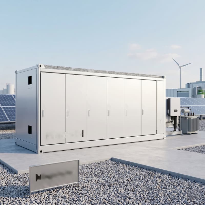
For users deploying in high-altitude locations below 4,000m: the MegSolid Containerized Energy Storage System 5000INTL has a rated altitude ceiling of ≤4,000m (protection rating IP55), providing direct coverage for high-altitude C&I scenarios.
V. Commercial Case Study: Food Processing Plant Backup Power ROI Analysis Module
Quantifying Production Downtime Costs and the Power Security Baseline
The cost of a power outage in a food processing environment is not just a lost electricity bill — it is a set of concurrent loss chains:
Cold chain disruption risk: Cold storage temperature rises approximately 3°C–5°C per hour after the compressor shuts down (depending on insulation grade and cargo density). If an outage exceeds 2 hours without backup power, cold chain food items (meat, dairy, seafood) may cross food safety thresholds, and writing off the entire batch is a routine outcome, not an extreme scenario.
Fresh raw material spoilage rate: For a mid-sized food processor with a daily output of 20 tons, assuming raw material inventory value of approximately ¥800,000, a 4-hour outage without backup power typically results in 30%–60% spoilage of cold chain materials — a direct loss of ¥240,000–¥480,000. This excludes commercial losses from order breaches.
Precision equipment restart losses: Restarting filling lines, sealing machines, and PLC control systems after an uncontrolled power loss requires manual calibration and test runs, typically taking 30 minutes to 2 hours. Where mold-heating equipment is involved, restart energy consumption is additionally layered on.
The power security baseline requirements for a food processing plant: continuous outage tolerance < 10ms (at the precision equipment level), minimum backup power duration ≥ 4 hours (for cold chain protection).
CAPEX and OPEX Structure Breakdown
Using a mid-sized food processor with average daily consumption of 1,500 kWh and peak power demand of 200 kW as a benchmark, the following compares two backup power solutions side by side:
Solution A: Conventional Diesel Generator Set (500 kVA)
|
Cost Item |
Value (Reference Range) |
|---|---|
| Equipment procurement (generator set + accessories) | ¥350,000–¥500,000 |
| Annual fuel consumption (average 200h of operation per year) | ¥80,000–¥120,000 |
| Annual scheduled maintenance (oil changes, filters, testing) | ¥15,000–¥25,000 |
| 10-year overhaul (engine TBO) | ¥80,000–¥150,000 (one-time) |
| Noise and emissions compliance modifications | ¥30,000–¥80,000 (subject to local regulations) |
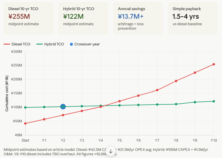
| 10-year total cost of ownership (including CAPEX) | Approx. ¥2,000,000–¥3,100,000 |
Solution B: PV-Storage Hybrid Inverter System (MegSolid Solution)
Using MegSolid R50KH3 (50 kW hybrid inverter) × 4 units + MegSolid Hybrid Solid-State ESS (261.24 kWh) × 2 systems as the baseline configuration, covering 200 kW backup power + approximately 522 kWh of storage capacity:
|
Cost Item |
Value (Reference Range) |
|---|---|
| Equipment procurement (inverters + storage + installation) | ¥800,000–¥1,200,000 |
| Annual O&M (remote monitoring + annual inspection) | ¥10,000–¥20,000 |
| Cell replacement cycle (8,000 cycles @ 80% DOD) | Approx. 15–20 years, far exceeding conventional solutions |
| Auxiliary energy consumption (liquid cooling system, etc.) | Significantly lower than diesel generator |
| 10-year total cost of ownership | Approx. ¥1,000,000–¥1,450,000 |
- Note: The figures above are engineering estimation reference ranges. Actual quotations must be determined based on specific project configurations, installation conditions, and local electricity prices.
Dynamic Model for Calculating Overall Return on Investment (ROI)
Returns from the PV-storage hybrid solution come from two independent channels, which combine to form the actual ROI:
Channel 1: Peak-Valley Arbitrage (Peak Shaving)
Using C&I electricity prices on China's eastern coast as a reference, the peak-valley price spread is approximately ¥0.6–¥1.2/kWh (varying by province and time-of-use period).
With 261.24 kWh × 2 systems = 522 kWh of available storage, completing one full charge-discharge cycle per day (at 90% efficiency):
- Daily arbitrage volume: 522 kWh × 0.9 = 469.8 kWh
- Daily arbitrage revenue (at ¥0.8/kWh spread): approximately ¥375/day
- Annual arbitrage revenue: approximately ¥137,000/year
Channel 2: Outage Loss Prevention
Assuming the plant experiences an average of 4 unplanned outages per year, each lasting approximately 2 hours:
- Without backup power, the comprehensive loss per outage (cold chain + restart + order delays) is conservatively estimated at ¥50,000–¥150,000
- Annual outage risk losses: ¥200,000–¥600,000
- With backup power coverage, losses drop to approximately ¥0 (switchover time <10ms, cold chain continuously protected)
Payback Period Projection:
|
Incremental CAPEX |
Annual Combined Returns (Arbitrage + Loss Prevention) |
Simple Payback Period |
|---|---|---|
| ¥800,000–¥1,200,000 (incremental vs. diesel solution approx. ¥450,000–¥700,000) | ¥337,000–¥737,000/year | Approx. 1.5–4 years |
- Peak-valley arbitrage revenue is a continuous income stream. The 8,000-cycle lifespan corresponds to approximately 15–20 years of operation, giving the long-term IRR a significant advantage over conventional diesel backup solutions.
VI. Deployment Execution Recommendations
Requirements Assessment Checklist
Before locking in equipment model selection, the project lead should complete the following engineering verification:
Load side:
- Confirm maximum demand power (kW) and total average daily energy consumption (kWh)
- Identify equipment sensitive to EPS switchover time (variable frequency drives, precision sensors, CNC machines, etc.)
- Confirm minimum continuous power supply requirements and outage tolerance duration for cold chain equipment
- Assess the proportion of non-linear loads (VFDs, etc.) and evaluate the impact of THDi on the grid (MegSolid Outdoor Cabinet system specification: THDi < 3%)
Grid side:
- Log the number, duration, and type of outages over the past 12 months (scheduled vs. fault-driven)
- Confirm local peak-valley electricity pricing periods and spread data
- Assess grid voltage stability (whether frequent voltage sags or harmonic exceedances are present)
- Confirm grid connection permit requirements and local utility's energy storage interconnection standards
Installation side:
- Measure available installation space (MegSolid Hybrid Solid-State C&I System: 1300×1350×2200mm / MegSolid Outdoor Cabinet large model: 2450×1550×2400mm)
- Confirm floor load-bearing capacity (MegSolid Outdoor Cabinet 100kW model net weight approx. 3,900 kg)
- Assess ventilation or liquid-cooling heat dissipation conditions (outdoor models rated IP54/IP55 for direct outdoor deployment)
- Confirm maximum site altitude (MegSolid Containerized 5000INTL ceiling: ≤4,000m)
System configuration:
- Confirm whether an existing PV system needs to be integrated (select AC-coupled vs. DC-coupled approach accordingly)
- Confirm the battery operating-voltage window. The proposed battery must remain within the R50KH3 150–800 V range under the relevant operating conditions; verify BMS communication and the complete system interface before quotation.
- Confirm on-grid/off-grid requirements and whether islanding operation capability is needed
- Define monitoring system requirements: local LCD display, remote cloud monitoring, SCADA integration protocols
FAQ
Q1: What is the core difference between AC-coupled and DC-coupled battery storage?
In AC coupling, the battery connects to the AC side of the system — solar DC is first converted to AC by the string inverter, then converted back to DC by a separate battery inverter for storage. DC coupling, as used in hybrid inverters, charges the battery directly from the solar DC bus without that intermediate conversion. The practical consequence is one fewer conversion stage, translating to 3–8% higher round-trip efficiency and a single control loop for both MPPT and battery SOC management.
Q2: The MegSolid R50KH3 lists a battery voltage range of 150–800V. Why does this range matter?
Battery voltage compatibility determines which storage modules a hybrid inverter can interface with without additional boost or buck converters.The 150–800 V range defines the battery-voltage window that R50KH3 can accept. Match the inverter to the battery’s complete operating-voltage range, not its nominal voltage alone. A battery system that operates above 800 V requires a separately verified power-conversion solution. A narrow voltage window would force engineering workarounds — wider range means more system design flexibility with fewer additional components.
Q3: What happens to production when the grid fails if I use a conventional string inverter?
Anti-islanding protection forces the inverter offline within milliseconds of detecting grid voltage loss — regardless of whether the PV array is producing at full capacity. There is no battery buffer to bridge the outage, and no load-shifting capability. Output goes to zero until grid power is restored.
Q4: How does the hybrid inverter's <10ms switchover time protect food processing equipment?
Variable frequency drives (VFDs), servo controllers, and precision instrumentation typically have undervoltage protection thresholds that trigger restarts when power drops for more than 10–20ms. A switchover time of <10ms — the specification for the MegSolid R50KH3 — keeps the power gap below that threshold. The load experiences no detectable interruption, so there is no automated restart, no recalibration cycle, and no additional wear from cold-start thermal stress.
Q5: Is the MegSolid 8,000-cycle life figure achievable under real operating conditions?
The 8,000-cycle rating (80% DOD) is a cell-level specification measured under controlled laboratory conditions. Real-world lifespan depends heavily on charge/discharge quality — specifically, whether the charging current remains stable during variable irradiance and whether the BMS receives coherent state-of-charge data. In a multi-device AC-coupled setup, communication frame delays (50–200ms) introduce current command jitter that causes micro-cycling degradation. A native hybrid inverter-BMS integration eliminates that jitter, making the nameplate figure more achievable in the field.
Q6: What is the minimum system size where a hybrid inverter starts to make financial sense over an AC-coupled retrofit?
There is no universal threshold — it depends on the remaining useful life of the existing inverter and how sensitive the load is to EPS switchover time. As a practical guideline: if the existing string inverter has less than 5 years of life remaining, or if the facility requires switchover times under 20ms (precision manufacturing, cold chain), the capital efficiency of a full hybrid system generally exceeds patching in a separate battery inverter within 3–5 years.
Q7: How does the hybrid solid-state technology affect the inverter's charge/discharge strategy?
Conventional liquid LFP requires conservative charge rate margins to prevent thermal runaway — the BMS must buffer uncertainty about how fast the electrolyte can safely absorb energy. Because the hybrid solid-state architecture physically eliminates the liquid decomposition pathway, the thermal runaway trigger condition does not exist at the material level. This means charging curves can be optimized for efficiency without the same protective margin requirements, allowing the inverter's MPPT algorithm to pursue higher instantaneous charge rates when solar irradiance conditions permit.
Q8: Can the MegSolid outdoor cabinet system (ESSA series) connect directly to a hybrid inverter?
The ESSA series (ESSA0030B through ESSA0100B-0215) is an all-in-one system with an integrated PCS rated at 30–100kW AC output. It is designed as a standalone C&I unit with its own grid interface, not as a battery module intended for connection to an external inverter. For projects requiring a separate inverter-plus-storage architecture with the MegSolid hybrid solid-state ESS (261.24 kWh), the appropriate counterpart is the MEGA0XXX TS power conversion system series or the R-series three-phase hybrid inverters, depending on scale and whether isolation transformer integration is required.
Q9: What does the THDi <3% specification on the outdoor cabinet system mean for grid compliance?
Total Harmonic Distortion of Current (THDi) measures how much harmonic pollution a device injects into the grid. Most regional grid codes for commercial and industrial interconnection require THDi below 5%, and stricter jurisdictions or sensitive grid segments may demand 3% or lower. The MegSolid ESSA series' on-grid THDi specification of <3% means it meets the more demanding compliance threshold without requiring additional line filters. This is relevant for facilities in industrial zones where multiple non-linear loads (VFDs, arc furnaces) already push the local grid harmonic baseline higher.
Q10: What altitude limitation applies to the MegSolid containerized systems, and why does it matter?
The MegSolid Containerized Energy Storage System 5000INTL is rated for deployment at altitudes up to 4,000m (IP55). Air density decreases with altitude, which affects both the thermal performance of air-cooled components and the dielectric strength of high-voltage insulation. The 4,000m ceiling means the system's electrical clearances, cooling capacity, and derating factors have been validated for high-plateau environments — relevant for projects in locations such as the Tibetan Plateau, Yunnan highlands, Andes, or East African rift regions. For installations above 4,000m, engineering consultation and custom derating are required.
