 Skip to content

When evaluating a solar storage unit or commercial battery datasheet, confusing nominal capacity with rated capacity, or failing to distinguish charge capacity (Ah) from nominal energy (kWh), measured discharge energy, and net usable AC energy, can leave a project short of its required peak-shaving or backup duration. Under international battery standards such as IEC 62620, IEC 62619, and UL 1973, nominal capacity and rated capacity (often searched as rating capacity) refer primarily to electric charge in Amp-hours (Ah), whereas energy storage system sizing requires converting those figures into kilowatt-hours (kWh) across defined voltage windows, discharge rates, and conversion efficiencies.
Whether you are sizing a 215.04 kWh ESSA cabinet (280Ah LFP), a 261.24 kWh Energon liquid-cooled LFP cabinet (314Ah LFP), or a 5,015.9 kWh utility container from our Commercial & Industrial (C&I) Energy Storage lineup, or selecting a 51.2V 314Ah storage unit from our Residential Energy Storage Systems range, this engineering guide explains the exact definitions, equations, and BMS operating boundaries that govern deliverable kilowatt-hours.
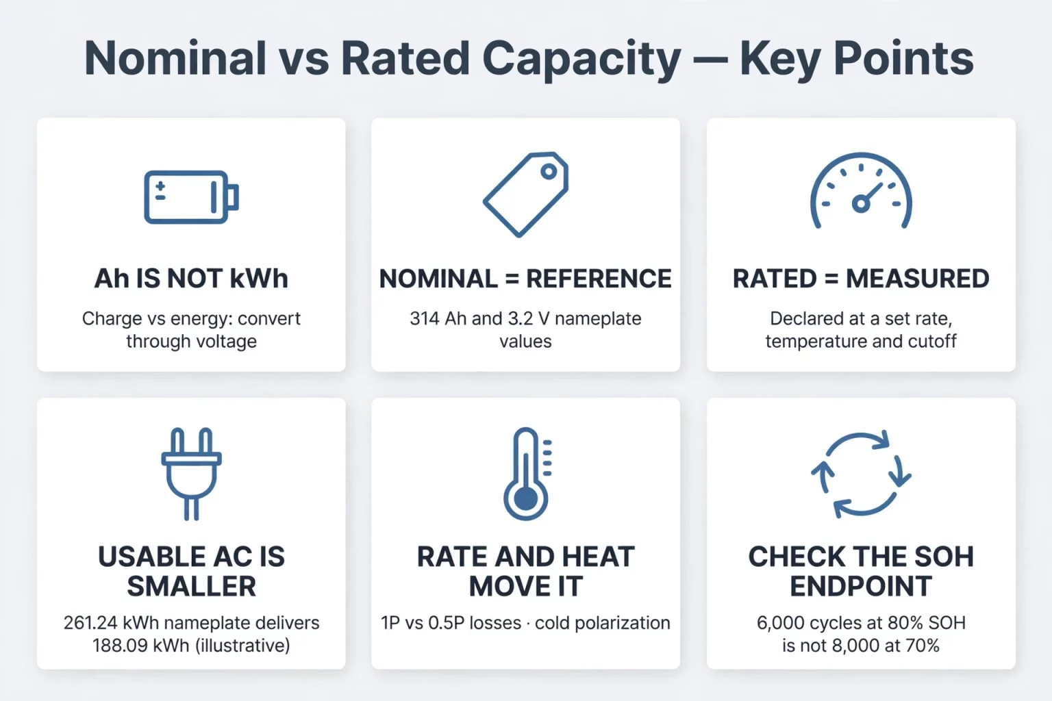
What Is Battery Capacity? Distinguishing Ah Capacity, Nominal Energy, and Usable kWh
Before comparing commercial storage proposals, procurement engineers and solar installers need a precise answer to two foundational questions: what is battery capacity, and why do cell and system datasheets list different values for Amp-hours (Ah) and kilowatt-hours (kWh)?
When someone asks what is a battery capacity in electrochemical engineering, the answer requires separating coulombic charge from electrical energy and specifying the exact time unit (t in hours vs. seconds):
- Electric Charge Capacity (Ah, Amp-hours): The quantity of electric charge delivered when a cell or battery discharges between specified cutoff voltages under defined test conditions. If time t is measured in hours (h), capacity is ∫ I(t) dt; if a BMS or laboratory cycler samples time in seconds (s), the integral is divided by 3,600:
C_Ah = ∫(t₀ to t_cut) I(t) dt (hours) = (1 / 3600) × ∫(t₀ to t_cut) I(t) dt (seconds)
- Electrical Discharge Energy (Wh or kWh): The time integral of terminal voltage multiplied by discharge current, which governs how long a storage system can supply an AC load measured in kilowatts (kW):
E_Wh = ∫(t₀ to t_cut) V(t) × I(t) dt (hours) = (1 / 3600) × ∫(t₀ to t_cut) V(t) × I(t) dt (seconds)
To eliminate ambiguity between IEC 62620 cell terminology and system-level BESS engineering, Table 1 defines the six distinct parameters that must be separated during technical due diligence.
Table 1: Six Core Voltage, Capacity (Ah), and Energy (kWh) Definitions in BESS
| Parameter | Standard Engineering Definition (IEC 62620 / BESS Practice) | Unit & Governing Formula | Cell-Level Example (SHS180-314Ah Cell Sheet) | System-Level Example (Energon / 51.2V Units) |
|---|---|---|---|---|
| 1. Nominal Voltage (V_nom) | Approximate reference voltage used to designate or identify a cell or battery system. | Volts (V) | 3.2V nominal per cell | 51.2V (16S inferred); 832V (Energon 1P260S) |
| 2. Nominal Capacity (C_nom) | Reference charge quantity used by a manufacturer to identify cell or battery scale. | Amp-hours (Ah) | 314Ah class reference | 314Ah (Energon, MG 512314, MEG-Solid-512314FL1); 280Ah (ESSA0100B-0215) |
| 3. Rated Capacity (C_rated / Rating Capacity) | Per IEC 62620, the capacity value (Ah) determined under specified conditions and declared by the manufacturer. | Ah verified under specified rate, temp & cutoff voltage | 314Ah rated capacity (standalone SHS180-314Ah cell spec) | 314Ah declared capacity on MEG-Solid-512314FL1 and MG 512314 |
| 4. Nominal Energy (E_nom) | Reference electrical energy estimated or designated from nominal voltage and capacity. | Wh or kWh; E_nom = N_s × V_nom × C | 3.2V × 314Ah = 1,004.8 Wh (theoretical product) | 260 × 3.2V × 314Ah = 261.248 kWh (Energon lists 261.24 kWh); 16 × 3.2V × 314Ah = 16,076.8 Wh (MG 512314 lists 16,076 Wh) |
| 5. Measured / Rated Energy (E_dis) | Electrical energy delivered or declared under specified discharge test conditions. | Wh or kWh; ∫ V(t)I(t) dt | 1,005 Wh rated energy on SHS180-314Ah cell spec (@ 0.5P, 25^°C) | System-level energy verified per model FAT protocol and operating voltage window |
| 6. Usable AC Energy (E_usable_AC) | Net energy delivered to the AC point of coupling after SOC window, PCS loss & auxiliaries. | kWh; E_installed × DoD × η_del | N/A (cell is DC only) | Illustrative 188.09 kWh on Energon (at 80% DoD & assumed 90% delivery efficiency) |
Engineering Notes on Table 1:
- Separating Cell-Level Specifications from System-Level Ratings: The standalone SHS180-314Ah hybrid solid-liquid cell specification sheet lists both a rated capacity of 314Ah and a rated energy of 1,005 Wh (compared to the theoretical nominal product 3.2V × 314Ah = 1,004.8 Wh). This cell-level specification is distinct from system-level datasheets (such as the standard LFP Energon 261.24 kWh cabinet or MEG-Solid-512314FL1 16.07 kWh unit) and cannot be automatically transferred across product lines without verifying the exact cell model installed in each system.
- Illustrative Usable AC Energy vs. Official System Efficiency: In Row 6 of Table 1, 261.24 kWh × 0.80 × 0.90 = 188.09 kWh (or 211.60 kWh at 90% DoD) is an illustrative calculation demonstrating how Depth of Discharge (DoD) and conversion losses reduce deliverable AC output. The 90% figure used in that formula is a hypothetical calculation input; engineers must not substitute the Energon datasheet's 90% maximum efficiency rating directly for site-measured AC delivery efficiency without accounting for load factor, transformer losses, and auxiliary liquid-cooling consumption.
- Factory Cell Grading and Batch Verification: During manufacturing, cells undergo formation grading to group units by capacity, open-circuit voltage (OCV), and internal resistance. Because specific sorting tolerances and minimum acceptance floors depend on factory quality standards for each production batch, EPC buyers should request the batch inspection criteria and Factory Acceptance Test (FAT) reports during procurement.
Nominal Capacity Definition & Rated Capacity Calculation for 314Ah BESS
To interpret laboratory test reports from IEC 62620, IEC 62619, UL 1973, or GB/T 36276-2023 accurately, buyers must understand how discharge rate protocols and voltage cutoff boundaries separate nominal reference values from measured test outputs.
The Formal Nominal Capacity Definition vs. Nominal Energy
In battery standards, the formal nominal capacity definition is the reference value of electric charge (expressed in Amp-hours, Ah) designated by the manufacturer to identify a cell or battery system. When manufacturers multiply that nominal or rated Ah capacity by the cell's nominal reference voltage (3.2V for LiFePO4 and hybrid solid-liquid LFP) and the number of series cells (N_s), the resulting product (N_s × 3.2V × Ah) is properly termed Nominal Energy (Wh or kWh), even though commercial brochures frequently refer to both Ah and kWh loosely as "capacity."
During an actual discharge cycle at 25^°C, a cell's terminal voltage is not fixed at 3.2V. As an illustrative profile, rested open-circuit voltage starts near 3.35V to 3.40V, transitions across an illustrative two-phase plateau around 3.20V to 3.32V through the middle of the discharge curve, and drops steeply toward the lower cutoff voltage near the end of discharge. Consequently, actual measured discharge energy (∫ V(t)I(t) dt) varies with discharge power and temperature.
Why Rated Capacity and Deliverable Energy Change with C-Rate and P-Rate
While individual cells and low-voltage batteries are often rated under Constant Current (C-rate, where 0.2C on a 314Ah unit equals 62.8A and 0.5C equals 157A), utility and commercial storage standards (such as GB/T 36276-2023) typically evaluate stationary BESS cells and cabinets under Constant Power (P-rate):
- Constant Power Current Escalation (I = P / V): When a factory dispatches a BESS to shave a constant kilowatt demand peak, the Power Conversion System (PCS) regulates constant power rather than constant current. As string voltage declines from the upper plateau toward the lower discharge knee, maintaining constant power requires DC current (I = P / V_string) to rise progressively during the latter half of discharge.
- Internal Joule Heating and IR Voltage Drop: Every cell has internal resistance. On MegSolid's standalone SHS180-314Ah hybrid solid-liquid cell specification sheet (which requires verification against original cell documentation per contract), AC internal resistance is 0.18 ± 0.03 mΩ and DC internal resistance is 0.4 ± 0.1 mΩ, achieving a cell energy efficiency of ≥ 94.5% at 0.5P. Under higher discharge power (such as 1P frequency regulation duty versus 0.5P 2-hour dispatch), internal resistive heating (I^2 R_DC) and terminal voltage polarization (I × R_DC) increase.
- Cell Test Cutoff Voltage vs. System Operating Voltage Window: Under load, terminal voltage equals open-circuit voltage minus resistive polarization (V_term = V_OCV - I × R_DC), causing higher discharge rates to reach the lower voltage cutoff earlier. Crucially, engineers must distinguish cell-level test cutoff voltages from system-level BMS operating voltage windows:
- — While the standalone SHS180-314Ah cell specification defines a cell test voltage window of 2.50V to 3.65V (above 0^°C), complete MegSolid battery units operate within narrower system voltage windows to protect longevity.
- — Specifically, the MEG-Solid-512314FL1 (51.2V / 314Ah) operates across 43.2V to 57.6V (corresponding to an average of approximately 2.70V to 3.60V per cell across an inferred 16-cell string), and the Energon (261.24 kWh) operates across 676V to 936V (corresponding to 2.60V to 3.60V per cell across its 1P260S string). Therefore, cell-level 2.50V to 3.65V test limits must never be assumed as the pack-level BMS cutoff window for every MegSolid system.
Lithium vs. Lead-Acid: Comparing Rated Capacity and Usable Energy
In residential solar backup and off-grid commercial inquiries, buyers frequently search: what is better a lithium battery or high capacity battery?
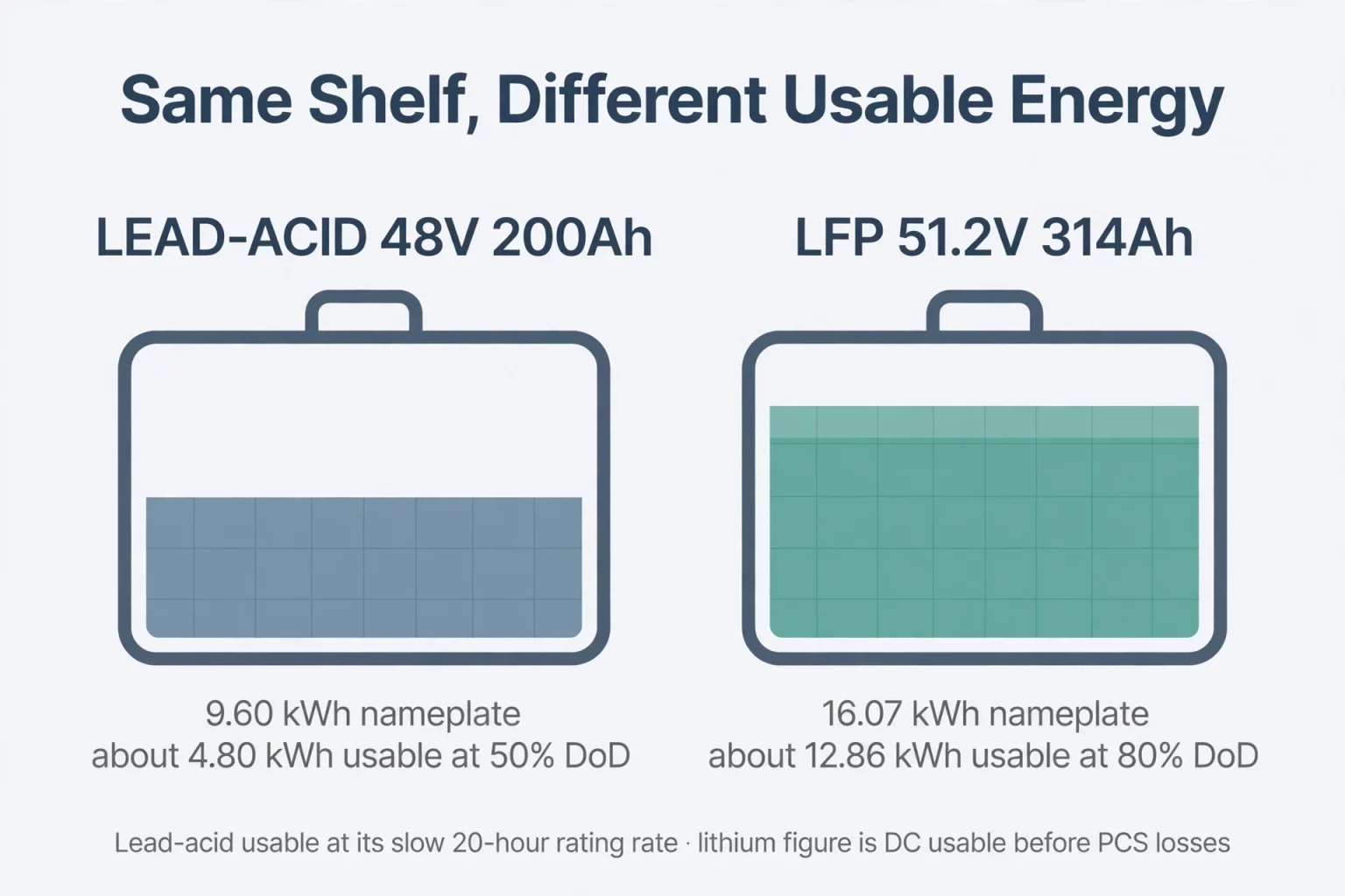
Because "lithium battery" (an electrochemical family) and "high capacity battery" (an Amp-hour or kilowatt-hour scale) are not mutually exclusive concepts, this question stems from traditional solar distributors comparing a "200Ah High-Capacity Lead-Acid (AGM/Gel) Battery" against a "100Ah Lithium (LiFePO4) Battery." Evaluating rated capacity versus usable energy across these technologies highlights three engineering differences:
1. Practical Depth of Discharge Management (80%+ Lithium DoD vs. Common 50% Lead-Acid Practice)
While lead-acid batteries can physically discharge below 50% State of Charge during emergencies, routine deep cycling below 50% DoD accelerates lead-sulfate crystallization and grid corrosion. As a common lifecycle management strategy to achieve 400 to 800 cycles, off-grid engineers typically restrict lead-acid banks to 50% daily DoD, meaning a 200Ah lead-acid bank provides roughly 100Ah of routine daily cycling charge. By contrast, lithium iron phosphate and hybrid solid-state LFP units are rated for long-term cycling at 80% to 100% DoD (such as 8,000 cycles at 80% DoD on the MEG-Solid-512314FL1 or ≥ 6,000 cycles at 80% EOL on the MG 512314).
2. High-Rate Discharge Behavior and Peukert Effect Reference Ranges
Lead-acid datasheets typically declare rated capacity over a slow 20-hour discharge (0.05C, or 10A for a 200Ah bank). Under Peukert's empirical relationship (t = H (C / (I × H))^k), typical literature reference values for the Peukert exponent k fall around 1.15 to 1.30 for lead-acid cells versus roughly 1.01 to 1.03 for lithium-ion cells (exact exponents vary by plate construction, temperature, and model). When an inverter draws a 0.5C surge load, acid diffusion limitations inside porous lead plates cause terminal voltage to drop rapidly toward the inverter low-voltage cutoff, reducing effective single-cycle deliverable energy compared to the 20-hour rating.
3. Model-Specific Cell Capacities Across MegSolid's Product Portfolio
Modern lithium storage systems combine lithium electrochemistry with high single-cell Amp-hour ratings, though buyers must note the exact cell capacity assigned to each specific MegSolid product line rather than assuming all systems share the same cell:
- Residential 51.2V 314Ah Systems: Both the MEG-Solid-512314FL1 (51.2V / 314Ah / 16.07 kWh hybrid solid-state LiFePO4 unit) and the MG 512314 (51.2V / 314Ah / 16,076 Wh movable unit, which supports up to 6 units in parallel) use 314Ah cells. (Note: Parallel expansion up to 6 units is officially specified for the MG 512314; parallel capability for the MEG-Solid-512314FL1 is not published on the general datasheet and should be confirmed with MegSolid per project.)
- C&I Outdoor Cabinets (ESSA vs. Energon): In MegSolid's C&I lineup, the ESSA0100B-0215 (100 kW / 215.04 kWh) uses 280Ah standard LFP cells (with optional project-specific solid-state configurations), whereas the liquid-cooled Energon (125 kVA / 261.24 kWh) uses 314Ah standard LFP cells in a 1P260S string.
- Utility Container (5000INTL): The 5,015.9 kWh / 2,700 kW 5000INTL container lists the SHS180-314 battery type code in its system table; exact cell electrolyte architecture and specification details for a given container contract should be verified directly with MegSolid rather than inferred solely from the type code.
Table 2 compares a legacy 48V 200Ah lead-acid bank against a typical 51.2V 100Ah LFP unit and MegSolid's two 51.2V 314Ah storage models.
Table 2: 48V Lead-Acid vs. 51.2V 100Ah LFP vs. MegSolid 51.2V 314Ah Units
| Comparison Parameter | 48V 200Ah Lead-Acid Bank (Typical AGM/Gel) | Typical 51.2V 100Ah LFP Unit (Industry) | MEG-Solid-512314FL1 (Hybrid Solid-State) | MG 512314 (Movable Residential Unit) |
|---|---|---|---|---|
| Declared Capacity & Nominal Energy | 200Ah (@ C_20) / 9.60 kWh | 100Ah / 5.12 kWh | 314Ah / 16.07 kWh (43.2–57.6V) | 314Ah / 16,076 Wh (40–58.4V) |
| Typical Daily DoD Strategy | ~50% DoD common practice for cycle life | 80% to 90% DoD | 80% DoD rated cycle baseline | 80% EOL cycle baseline (@ 25^°C) |
| Illustrative DC Usable Energy (at 80% / 50% DoD) | ~4.80 kWh at 0.05C (drops under higher C-rate depending on cutoff V & temp) | ~4.10 kWh DC at 80% DoD | ~12.86 kWh DC at 80% DoD (~11.57 kWh AC at assumed 90% efficiency) | ~12.86 kWh DC at 80% DoD (parallel up to 6 units / 96.46 kWh nominal) |
| Rated Cycle Life | 400 to 800 cycles (typical at 50% DoD) | 4,000 to 6,000 cycles (at 80% DoD) | 8,000 cycles @ 80% DoD | ≥ 6,000 cycles (@ 25^°C, 80% EOL) |
| Charge / Discharge Current & Impedance | 20A to 40A typical continuous | 50A to 100A typical | 200A max charge / 200A continuous discharge; ≤ 15 mΩ | 200A max charge / 200A max discharge; ≤ 80 mΩ assemblage |
Engineering Note on Current Ratings in Table 2:
- Continuous vs. Maximum Current and Nominal DC Power Calculation: On official datasheets, the MEG-Solid-512314FL1 specifies 200A maximum charge and 200A continuous discharge current, whereas the MG 512314 table lists 200A maximum charge and 200A maximum discharge current without stating a separate continuous discharge figure. Multiplying 200A × 51.2V = 10.24 kW represents only the theoretical DC power at nominal voltage; actual continuous AC output power depends on terminal voltage under load, continuous thermal limits, and hybrid inverter efficiency.
4 Engineering Factors That Influence Deliverable BESS Capacity in the Field
In real-world operation, the deliverable energy of a commercial cabinet or residential battery bank is governed by series string voltage cutoffs, internal impedance, ambient temperature polarization, and End-of-Life (EOL) State of Health (SOH) definitions.
1. Series String Cutoff Dynamics ("Barrel Effect") and Thermal Uniformity
In a high-voltage commercial cabinet such as the 261.24 kWh Energon (which connects 260 cells of 314Ah LFP in a 1P260S series string operating across 676V to 936V DC), all 260 cells carry the exact same series current:
- Charge Termination by the First Cell Reaching the Upper BMS Threshold: During charging, the string BMS terminates or tapers charge current as soon as the single highest-voltage cell reaches the BMS upper cell-voltage threshold, even if other cells in the string remain at a lower state of charge. (Note: In LFP cells, terminal voltage during active charge or discharge cannot be mapped to a fixed SOC percentage without accounting for C-rate polarization, temperature, and resting hysteresis.)
- Discharge Termination by the First Cell Reaching the Lower BMS Threshold: During discharging, the BMS disconnects the string as soon as the weakest or coldest cell drops to the lower cell-voltage cutoff, leaving unused charge stranded in the remaining 259 cells.
- Mitigating Differential Aging via Liquid Cooling: Because elevated cell temperatures accelerate solid-electrolyte interphase (SEI) growth, temperature gradients across a long series string cause hotter cells to lose capacity faster than cooler cells. Applying liquid cooling on the Energon (261.24 kWh) cabinet and a liquid-cooled chiller on the 5000INTL (5,015.9 kWh) container helps maintain tighter cell-to-cell temperature uniformity across the string than unconditioned air.
2. Internal Impedance and Load-Induced Voltage Drop
When an inverter supplies high-current loads, internal resistance creates an immediate voltage drop (Δ V = I × R_internal):
- Cell-Level Impedance: On its standalone cell specification sheet, the SHS180-314Ah hybrid solid-liquid cell specifies an AC resistance of 0.18 ± 0.03 mΩ and a DC resistance of 0.4 ± 0.1 mΩ.
- Unit-Level Impedance Boundary: On the MEG-Solid-512314FL1 (51.2V / 314Ah), internal impedance is specified at ≤ 15 mΩ (and ≤ 80 mΩ assemblage impedance on the MG 512314). While low internal impedance minimizes resistive voltage sag during high-current draw, whether a unit can sustain a 200A load without reaching its low-voltage cutoff (43.2V on MEG-Solid-512314FL1 or 40.0V on MG 512314) also depends on the instantaneous State of Charge, cell temperature, and BMS protection timers.
3. Low-Temperature Voltage Polarization vs. Charging Limits
Cold ambient temperatures increase electrolyte viscosity and slow lithium-ion diffusion, which increases internal resistance and voltage polarization during discharge:
- Sub-Zero Discharge Cutoff Adjustment: On the standalone SHS180-314Ah cell specification sheet, the operating voltage window is listed as 2.5V to 3.65V above 0^°C and expands to 2.0V to 3.65V at or below 0^°C. Lowering the sub-zero discharge cutoff to 2.0V compensates for the steeper resistive voltage polarization experienced during cold discharging so that usable energy is not cut off prematurely. (Note: Lithium plating is a separate phenomenon that occurs during low-temperature charging and must be prevented through BMS charge temperature limits, reduced charge current derating, and auxiliary heating.)
- System Operating Temperature Envelopes: At the system level, the ESSA outdoor C&I cabinet series operates from 0^°C to +45^°C, the liquid-cooled Energon cabinet operates from -20^°C to +55^°C (with output derating above 45^°C), and the PMA modular PCS series operates from -30^°C to +60^°C (derating above 45^°C).
4. End-of-Life (EOL) SOH Thresholds (80% SOH vs. 70% SOH)
When evaluating cycle life ratings, engineers must check the End-of-Life State of Health (SOH_EOL) boundary defined on the specification sheet:
- SHS180-314Ah Standalone Cell Specification: Lists 6,000 cycles to ≥ 80% SOH (@ 0.5P/0.5P, 100% DoD). Under theoretical conditions where other variables remain constant, 80% of a 314Ah initial rating corresponds to 251.2Ah of remaining capacity.
- SHS165-280Ah Standalone Cell Specification: Lists ≥ 8,000 cycles to ≥ 70% SOH (@ 0.5P/0.5P, 100% DoD at room temperature).
- Mandatory Verification Note: Because 80% SOH and 70% SOH represent different cumulative capacity-fade endpoints, the two cycle numbers cannot be directly ranked against each other without normalizing to the same EOL SOH threshold. Furthermore, because the standalone cell specification sheets for SHS180-314Ah and SHS165-280Ah are separate from the website's general system catalog (llms-full.txt), buyers must request the original cell specification documents and confirm which specific cell model is configured in their contracted system.
How to Size Installed Energy vs. Usable AC Energy for C&I & Residential Projects
To calculate the required Beginning-of-Life (BOL) installed energy (E_installed_required) needed to guarantee a target net AC load (E_target_AC_load), engineers apply the following sizing formula:
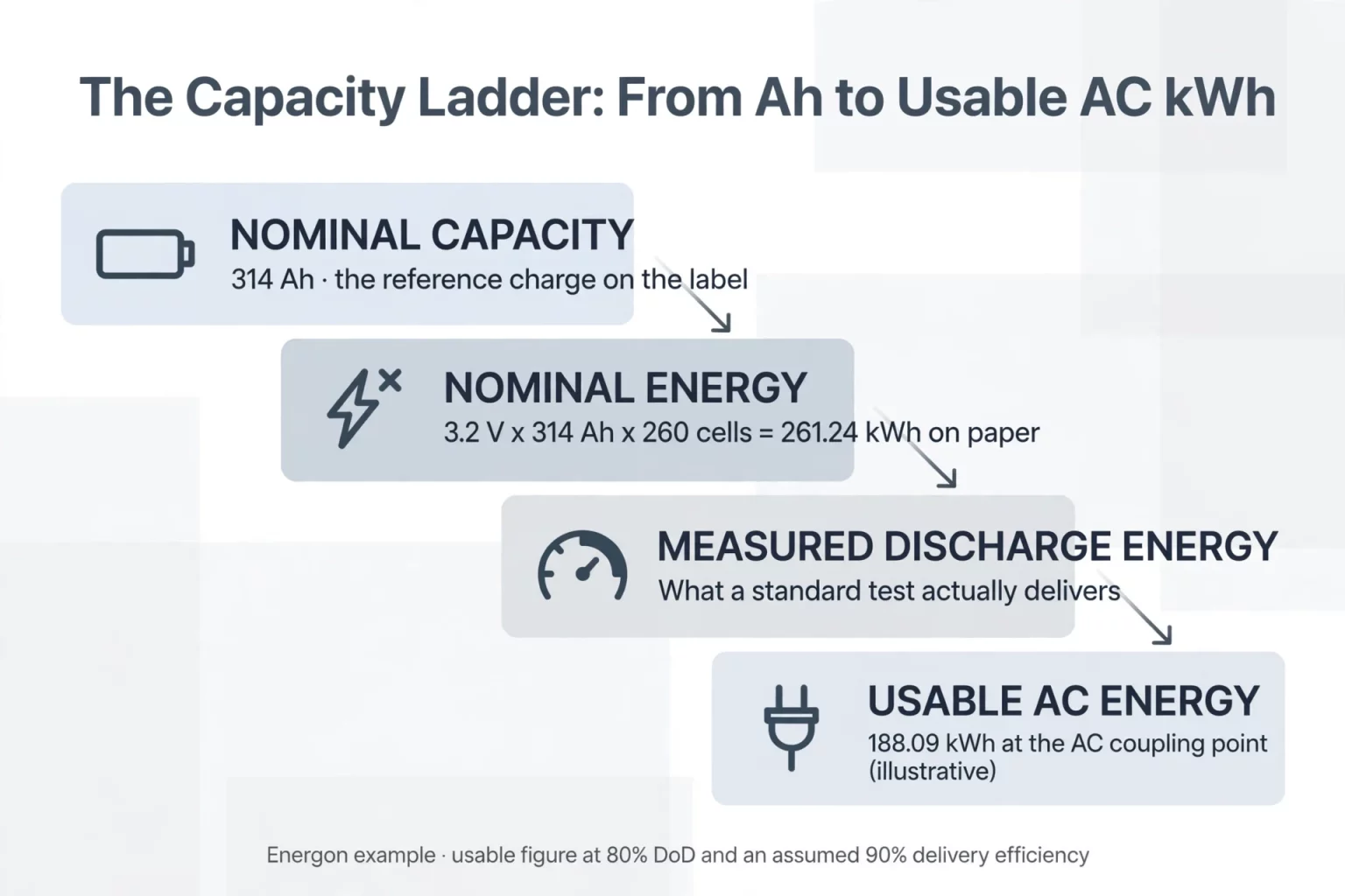
E_installed_required = E_target_AC_load / (DoD_design × η_del × SOH_target)
Table 3 summarizes MegSolid's official residential, C&I, and utility storage platforms alongside their confirmed voltage/cell configurations and efficiency boundaries.
Table 3: MegSolid Residential, C&I & Utility Storage Capacity Reference Matrix
| MegSolid Platform | Cell & String Configuration | Official Nameplate Energy / Power | Illustrative BOL Deliverable AC Energy (80% DoD, Assumed 90% Efficiency) | Official Efficiency & Application Notes |
|---|---|---|---|---|
| MEG-Solid-512314FL1 (51.2V Hybrid Solid-State) | 314Ah hybrid solid-state LFP (inferred 16S from 51.2V nominal; 43.2–57.6V) | 16.07 kWh / 51.2V (200A max charge & continuous discharge) | 11.57 kWh (illustrative per single unit) | IP21/IP65 options per order; confirm parallel rules & inverter efficiency per project |
| MG 512314 Movable Residential Unit | 314Ah cell (inferred 16S from 51.2V nominal; 40–58.4V; up to 6 units parallel) | 16,076 Wh per unit (up to 96.46 kWh nominal across 6 units) | 11.57 kWh per unit (69.45 kWh across 6 parallel units) | IP21 movable residential storage; 200A max charge/discharge rating |
| ESSA0100B-0215 Outdoor C&I Cabinet | 280Ah standard LFP (optional solid-state per contract; 672–850V DC) | 215.04 kWh / 100 kW (0.5C; ESSA series spans 55.3 to 215.04 kWh) | 154.83 kWh per cabinet | 400V AC, 0^°C to +45^°C, IP54; built-in isolation transformer |
| Energon Liquid-Cooled LFP C&I Cabinet | 1P260S string of 314Ah standard LFP cells (676–936V DC; up to 10 units) | 261.24 kWh / 125 kVA (832V DC nominal; 400V AC) | 188.09 kWh (at 80% DoD; 211.60 kWh at 90% DoD) | Max. efficiency 90% (datasheet peak); -20^°C to +55^°C (derates >45^°C) |
| 5000INTL 20-Foot Utility Container | Lists SHS180-314 battery type code (1,123.2–1,497.6V DC; 1,331.2V nominal) | 5,015.9 kWh / 2,700 kW (450 kW × 6 stages at 690V AC) | To be confirmed per project efficiency curve & chiller auxiliary load | Official Max. efficiency is 87.5% (datasheet peak); IP55 liquid-cooled chiller |
Critical Engineering Notes on Table 3:
- Why 5000INTL Should Not Use a 90% Efficiency Assumption: Although multiplying 5,015.9 kWh × 0.80 × 0.90 equals 3,611.45 kWh mathematically, MegSolid's official specification for the 5000INTL container lists a maximum efficiency of 87.5%. Using a 90% delivery efficiency assumption that exceeds the unit's published 87.5% maximum efficiency would overestimate deliverable AC energy. In practice, EPC engineers must model 5000INTL deliverable energy using a conservative project-verified delivery efficiency below the 87.5% peak ceiling (after deducting liquid-cooled chiller parasitic consumption and step-up transformer losses).
- Ceteris Paribus Condition for End-of-Life Capacity Sizing: Under theoretical conditions where temperature, C-rate, internal resistance, and auxiliary loads remain unchanged (ceteris paribus), a battery system reaching an 80% SOH end-of-life threshold experiences a 20% reduction in single-cycle deliverable energy compared to its beginning-of-life baseline. Because cell impedance typically rises as SOH declines, engineers should include an additional margin or scheduled augmentation plan when guaranteeing Year-10 AC output.
FAQ
What is the difference between nominal capacity, rated capacity, and nominal energy in a BESS?
Per IEC 62620 and stationary battery conventions: • Nominal Capacity (Ah) is the reference charge value used to identify the scale of a cell or battery. • Rated Capacity (Ah) is the capacity declared by the manufacturer to be delivered under specified temperature, charge/discharge rate, and cutoff voltage conditions. • Nominal Energy (Wh / kWh) is the reference energy calculated from nominal voltage and capacity (such as 260 × 3.2V × 314Ah = 261.248 kWh, listed as 261.24 kWh on the Energon datasheet), whereas Measured Discharge Energy (Wh / kWh) is the actual time-integrated energy (∫ V(t)I(t) dt) delivered during a standardized discharge test.
Why is usable AC energy lower than nameplate energy in a commercial BESS?
Usable AC energy at the point of coupling is lower than nameplate DC energy due to three factors: • Operating SOC / DoD Window: The BMS operates within a defined system voltage and state-of-charge window (commonly 80% to 90% DoD, such as 676V to 936V on Energon or 43.2V to 57.6V on MEG-Solid-512314FL1) to prevent over-charge and over-discharge. • Power Conversion and Transformer Losses: Bidirectional DC-to-AC conversion in the PCS and isolation/step-up transformers incurs energy losses. • Auxiliary Parasitic Consumption: Liquid cooling chillers, pumps, cabinet fans, BMS controllers, and fire protection panels draw auxiliary power during operation.
Does discharging a 314Ah BESS at 1P instead of 0.5P reduce its single-cycle deliverable energy?
Yes. Discharging at 1P (1-hour constant power rate) approximately doubles the DC current compared to 0.5P (2-hour rate). Higher current increases internal resistive losses (I^2 R_DC) and voltage polarization (I × R_DC), causing terminal voltage to reach the lower BMS cutoff boundary earlier in the discharge cycle. Engineers sizing a 1C cabinet (such as the 50 kW / 55.296 kWh ESSA0050B-0055) or evaluating 1P frequency regulation duty should always request the model-specific 1C / 1P discharge curve.
What is better: a lithium battery or a high-capacity lead-acid battery for solar backup?
Lithium storage systems (such as LiFePO4 or hybrid solid-state LFP) provide higher usable energy density and longer cycle life than legacy deep-cycle lead-acid banks of the same nameplate Ah rating. Lead-acid banks are commonly restricted to roughly 50% DoD to preserve cycle life (400 to 800 cycles) and experience steeper capacity reduction under higher C-rate loads due to the Peukert effect. Modern 51.2V 314Ah lithium units (MEG-Solid-512314FL1 at 16.07 kWh and MG 512314 at 16,076 Wh) deliver both high Ah capacity and 80% DoD daily cycling over 6,000 to 8,000 cycles.
Do all MegSolid C&I cabinets and containers use the same 314Ah cell?
No. Cell capacity and chemistry depend on the exact system model: • ESSA0100B-0215 (100 kW / 215.04 kWh): Uses 280Ah standard LFP cells (with optional project-specific solid-state cell configurations confirmed per contract). • Energon (125 kVA / 261.24 kWh): Uses 314Ah standard LFP cells in a 1P260S liquid-cooled string. • 5000INTL (2,700 kW / 5,015.9 kWh): References the SHS180-314 battery type code on its specification sheet; buyers should verify the exact cell specification sheet and electrolyte configuration assigned to their project contract.
How can EPCs verify a battery supplier’s rated capacity claim?
Request the exact cell or pack model datasheet, declared Ah value, discharge rate, test temperature, end-of-discharge voltage and FAT results. Verify whether the figure is a nominal reference, a manufacturer-declared rated capacity, a measured DC discharge result or usable AC energy at the site connection.
Why can two batteries with the same Ah rating deliver different kWh?
Amp-hours describe charge, while energy also depends on the voltage profile during discharge. Different nominal voltages, lower cutoff limits, discharge rates, temperatures and internal resistance can produce different measured Wh from batteries with the same Ah nameplate.
How should usable AC energy be calculated for an Energon 261 cabinet?
Start with the 261.24 kWh nameplate rating, apply the design DoD window and separately verified AC delivery efficiency, then account for auxiliary loads and end-of-life SOH. An illustrative 80% DoD and assumed 90% delivery efficiency yields 188.09 kWh; this is a sizing example, not a guaranteed output rating.
What changes when a BESS discharges at 1P instead of 0.5P?
At higher constant-power discharge rates, DC current and resistive losses increase, terminal voltage can reach the BMS cutoff earlier and measured delivered energy may decrease. Review the exact cell discharge curves, temperature conditions and complete-system power limits before sizing the PCS or expected run time.
Which information is needed to guarantee end-of-life battery runtime?
Specify the net AC load and required duration, design DoD, verified conversion and auxiliary losses, minimum EOL SOH, maximum operating C-rate, temperature range and BMS cutoff conditions. The SHS180 and SHS165 cycle ratings use different 80% and 70% SOH endpoints and cannot be compared directly.
Engineer Your Project with Verified Capacity Data from MegSolid
Sizing a commercial peak-shaving array or residential solar backup bank requires separating nominal Ah and kWh labels from verified deliverable AC energy. Whether your project requires a 55.296 kWh to 215.04 kWh ESSA outdoor cabinet, a 261.24 kWh Energon liquid-cooled LFP cabinet, a 5,015.9 kWh 5000INTL utility container, or a 51.2V 314Ah residential storage unit, MegSolid provides model-specific technical documentation and engineering support.
Contact our engineering team to review cell and system specification sheets and calculate deliverable kWh for your site load profile:
- For Factories, Microgrids & Commercial Peak Shaving (55kWh to 5MWh+): Explore full specifications and request a project-specific capacity assessment on our Commercial & Industrial (C&I) Energy Storage page.
- For 51.2V Home Solar Backup & Off-Grid Living (16.07kWh to 96.46kWh): Compare our 314Ah hybrid solid-state and movable home storage units on our Residential Energy Storage Systems page.
