
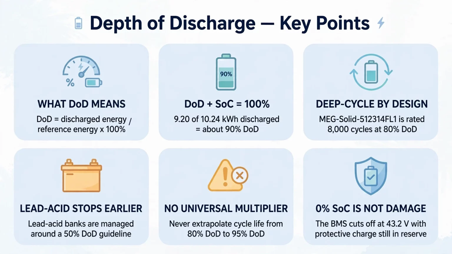
When sizing or operating a stationary deep discharge battery, depth of discharge (DoD) expresses how much of the battery's reference capacity or energy is actually discharged during a cycle. In simple engineering terms: DoD (%) = discharged energy ÷ reference energy capacity × 100%. This matters because cycle life, usable energy, backup duration and ROI all collapse when buyers compare nameplate kWh without checking the approved DoD test basis.
Across MegSolid's published portfolio, the MEG-Solid-512314FL1 hybrid solid-state residential battery is rated at 51.2V / 314Ah / 16.07 kWh and 8,000 cycles at 80% DoD, the MG 512314 movable 51.2V / 314Ah / 16.076 kWh unit is rated at ≥ 6,000 cycles at 25°C and 80% EOL, and the ESSA0100B-0215 outdoor C&I cabinet is rated at 100 kW / 215.04 kWh with ≥ 5,000 cycles. If you are reviewing Residential Energy Storage Systems, C&I Energy Storage Systems or Solid-State Energy Storage Systems, this guide separates routine deep-cycle operation from hazardous over-discharge below cutoff limits.
What Is a Deep Discharge Battery? DoD vs. State of Charge (SoC) Explained
When engineers search for what is deep discharge battery, two different meanings appear. Confusing those meanings leads to bad specs, bad warranty comparisons and bad operating settings.
Two Engineering Meanings of “Deep Discharge”
- 1. Deep-cycle design capability: In solar self-consumption, backup and peak shaving, a deep discharge battery is a battery designed to cycle across a large usable window, such as 80% DoD, over thousands of cycles.
- 2. Abusive over-discharge below the approved lower limit: In failure analysis, battery deep discharge means driving cells below the manufacturer's permitted cutoff voltage, for example below the 43.2V discharge cutoff listed on MEG-Solid-512314FL1 or below the 40.0V lower operating limit listed on MG 512314.
Core Formula: Depth of Discharge (DoD) and State of Charge (SoC)
On a consistent energy basis, DoD (%) = discharged energy ÷ reference energy capacity × 100%. Under the same calibrated baseline, the ideal relationship is DoD (%) + SoC (%) = 100%.
- Illustrative example: If a battery with 10.24 kWh reference DC energy delivers 9.20 kWh on the same DC basis, DoD = 9.20 ÷ 10.24 × 100% = 89.84%, approximately 90% DoD.
- Use one capacity basis only: Never divide AC metered output directly by DC nominal nameplate energy without accounting for inverter or PCS conversion losses, voltage sag and auxiliary loads.
- Displayed SoC is an estimate: BMS SoC is not a pure physical identity; it is an algorithmic estimate based on coulomb counting, voltage lookup, temperature and calibration.
How Battery Depth of Discharge Affects Cycle Life and Lifetime Energy Throughput
When buyers compare battery proposals only by upfront $/kWh, they usually miss the number that actually drives storage economics: how much energy the system can deliver across its approved DoD window before reaching the specified end-of-life condition.
Lifetime Throughput Formula and Comparability Boundaries
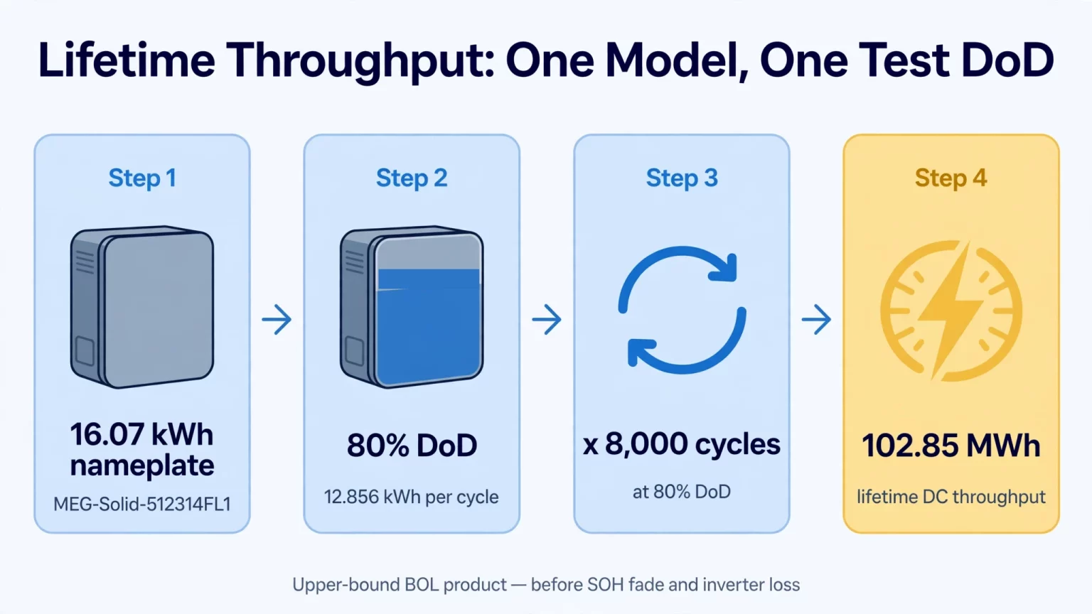
For one specific battery model tested at one stated DoD and rated cycle count, theoretical lifetime energy throughput can be expressed as: E_lifetime = N_cycles × E_per_cycle.
- No universal multiplier exists across chemistries or models: You cannot safely convert 8,000 cycles at 80% DoD into a guaranteed number at 90% or 95% DoD without model-specific test curves.
- Do not extrapolate beyond published ratings: MEG-Solid-512314FL1 is officially rated at 8,000 cycles at 80% DoD. That does not authorize claims of 8,000 to 10,000+ cycles at 95% DoD or 11,000+ cycles at shallow cycling.
- Capacity fade changes per-cycle energy: Simple multiplication gives an upper-bound beginning-of-life result. As SOH declines toward the end-of-life threshold, delivered energy per cycle also declines.
- Lead-acid follows different lifecycle practice: A 50% DoD guideline in lead-acid is a durability strategy, not a magic destruction threshold. Deep-cycle lead-acid can go deeper, but cycle life falls fast.
| MegSolid Model | Confirmed Voltage & Capacity / Energy | Confirmed Cell & Thermal Specification | Published Cycle Life & DoD Specification | Engineering Throughput & Sizing Note |
|---|---|---|---|---|
| MEG-Solid-512314FL1 (Residential) | 51.2V / 314Ah / 16.07 kWh (43.2–57.6V working range; 43.2V discharge cutoff) | Hybrid solid-state LiFePO4, 314Ah | 8,000 cycles @ 80% DoD | At 80% DoD, 12.856 kWh BOL DC per cycle; upper-bound BOL product = 102.85 MWh DC before SOH fade and inverter loss |
| MG 512314 (Movable Residential Unit) | 51.2V / 314Ah / 16.076 kWh (40.0–58.4V working range) | 314Ah battery, product page lists ≥ 314Ah @ 0.2C | ≥ 6,000 cycles @ 25°C, 80% EOL | Confirm test DoD percentage in controlled documentation before computing lifetime MWh |
| ESSA0100B-0215 (C&I Outdoor Cabinet) | 768V, 100 kW AC, 215.04 kWh, 672–850V DC | 280Ah LFP, 0.5C, intelligent air cooling | ≥ 5,000 cycles | Standard 280Ah LFP chemistry; verify test DoD and EOL boundary per contract |
| Energon 261 (Liquid-Cooled C&I Cabinet) | 832V, 125 kVA AC, 261.24 kWh, 676–936V DC | 314Ah LFP, intelligent liquid cooling | Verify project-specific cycle life, DoD window and SOH curve in controlled documentation | Confirm power factor, test condition and auxiliary load allowance |
| 5000INTL (20-foot Utility Container) | 1,331.2V, 2,700 kW AC, 5,015.9 kWh, 1,123.2–1,497.6V DC | SHS180-314 cell code; smart liquid cooling | Verify container-level cycle life, DoD and electrolyte category through controlled documentation | Do not infer electrolyte type only from the cell code |
How to Audit BESS Datasheets and Warranty Terms for DoD vs. Cycle Life
- 1. Check the test rate and temperature: Cycle life is only comparable when the underlying charge/discharge rate and ambient temperature are both stated explicitly.
- 2. Check the end-of-life criterion: Confirm whether the cycle count ends at 80% SOH, 70% SOH or 60% SOH. A bigger number attached to a softer EOL definition is not a better battery.
- 3. Check the PSoC window position: Two profiles can have the same DoD span but very different stress if one profile lives near the upper voltage knee.
- 4. Separate cell data from full-system data: A cell lab result is not the same as a complete cabinet or container rating where thermal gradients, cell spread and PCS efficiency dominate usable AC output.
Over-Discharge Risks: What Happens During a Deep Discharge of Battery Beyond Cutoff Limits?
Reaching 0% displayed SoC during a normal discharge cycle does not automatically mean the battery is damaged. Under normal operation, the inverter and the BMS stop discharge at the approved lower operating boundary while protective charge remains in the cells. Dangerous over-discharge begins only when the pack is driven below its allowed minimum, often because loads stay connected after cutoff or a depleted battery sits uncharged for too long.
Electrochemical Mechanism of Severe Over-Discharge
- Rising anode potential: In a lithium-ion cell, the negative electrode is coated on copper foil. During severe over-discharge, the negative electrode potential can rise enough to create copper dissolution risk.
- No single universal trigger voltage: There is no one fixed per-cell number that always marks the start of damage across all chemistries and temperatures. The risk depends on cell chemistry, temperature, duration and depth of over-discharge.
- Recharge hazard: If dissolved copper later redeposits during recharge, self-discharge, capacity loss or internal short-circuit risk can follow. A severely over-discharged pack must be professionally evaluated, not force-charged.
Three Protection Functions to Verify in BESS Engineering Design
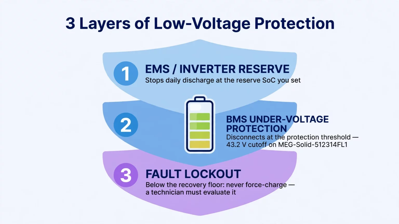
Because published working voltage windows are not the same thing as the internal hardware protection logic, engineers should verify the inverter reserve settings, the BMS under-voltage protection and the severe under-voltage fault recovery protocol separately.
| Protection Function Category | Engineering Purpose | Key Parameters to Verify per Model Documentation | Operational and Recovery Protocol |
|---|---|---|---|
| 1. EMS / Hybrid Inverter Operational SoC Reserve | Stops routine daily AC discharge while leaving a usable buffer above the battery’s lower voltage limit | User-programmable minimum SoC reserve, inverter low-voltage cutoff setting, and CAN or RS485 BMS communication | Inverter stops AC load discharge at the configured reserve while leaving PV and charger paths available for normal recovery |
| 2. Pack / Rack BMS Under-Voltage Protection | Disconnects or blocks discharge if pack or cell voltage reaches the BMS protection threshold | Published working voltage range plus separate BMS UVP trip and recovery specifications | Do not assume automatic wake-up; verify exact BMS reset and recovery logic in the model-specific manual |
| 3. Severe Under-Voltage Fault Lockout and Diagnostic Hold | Prevents unsafe charging if cells have fallen below the manufacturer’s permitted recovery floor | Cell-level severe lockout threshold, BMS quiescent current and self-discharge rate | Never attempt forced charging or DIY jump-starting; isolate loads and let MegSolid or a qualified technician inspect the pack |
Scenario Examples for Configuring Operational DoD and SoC Reserves
- Grid-tied solar self-consumption and TOU arbitrage: A daily reserve of 20% SoC, equivalent to 80% operational DoD, aligns with the published 8,000-cycle at 80% DoD test basis of MEG-Solid-512314FL1 while keeping margin above the 43.2V discharge cutoff.
- Frequent grid outage and backup priority: Where blackouts are common, operators may stop daily economic cycling at 30% to 40% SoC so the lower band remains reserved for emergency loads paired with a compatible hybrid inverter.
- Off-grid solar plus standby generator: Program the generator auto-start trigger above the inverter low-battery cutoff so the genset can start, stabilize and accept charging load before the battery reaches its lower discharge boundary.
For project teams comparing products, the right question is not “How deep can the battery go?” The real question is: “At what DoD, at what test conditions, to what end-of-life boundary, and with what protection logic?” That is how you protect lifecycle economics instead of buying a comforting but meaningless headline number.
If your site needs verified battery and inverter coordination, compare the MEG-Solid-512314FL1, MG 512314, ESSA outdoor cabinet range, Energon 261 liquid-cooled ESS and 5000INTL containerized storage against one another on the same engineering basis before you sign a procurement document.
FAQ
What does depth of discharge (DoD) mean in a battery energy storage system?
Depth of discharge is the percentage of a battery's reference capacity or energy that has been discharged during a cycle. If a 10.24 kWh reference battery delivers 9.20 kWh on the same DC basis, the DoD is about 90%. Buyers must confirm whether the basis is DC energy, AC energy or Ah and keep numerator and denominator on the same basis.
Is 80% DoD the same thing as 20% SoC?
Under the same calibrated reference baseline, yes: DoD plus SoC equals 100%. In practice, displayed SoC is a BMS estimate influenced by coulomb counting, voltage lookup, temperature and calibration, so it should not be treated as a perfect physical identity at every moment.
Does 0% displayed SoC mean the battery has been damaged by deep discharge?
No. In a correctly configured system, the inverter or BMS stops discharge at the approved lower operating boundary while protective charge still remains in the cells. Damage risk rises when the pack is left depleted for a long time or is forced below the manufacturer's minimum cutoff voltage.
What cycle life and DoD are officially listed for MEG-Solid-512314FL1?
The published MEG-Solid-512314FL1 specification lists 51.2V, 314Ah, 16.07 kWh, a 43.2V to 57.6V operating window, 43.2V discharge cutoff, and 8,000 cycles at 80% DoD. Those numbers apply to that model and that stated test basis only.
How much theoretical lifetime energy throughput does MEG-Solid-512314FL1 deliver at 80% DoD?
At 80% DoD, one cycle corresponds to 12.856 kWh of beginning-of-life DC energy. Multiplying by 8,000 cycles gives an upper-bound theoretical lifetime throughput of 102.85 MWh DC before SOH fade, inverter conversion losses and auxiliary consumption.
Can buyers extrapolate 8,000 cycles at 80% DoD into guaranteed performance at 90% or 95% DoD?
No. There is no universal multiplier that safely converts cycle life between different DoD windows across different chemistries and products. Any claim about higher or lower DoD operation must be backed by model-specific test data and warranty language, not sales extrapolation.
How is MG 512314 different from MEG-Solid-512314FL1?
Both are 51.2V 314Ah class products, but their published operating windows and cycle statements differ. MEG-Solid-512314FL1 lists 16.07 kWh, 43.2V to 57.6V, and 8,000 cycles at 80% DoD, while MG 512314 lists 16.076 kWh, 40.0V to 58.4V, and ≥ 6,000 cycles at 25°C and 80% EOL. They should not be treated as interchangeable without checking the specific application and inverter compatibility.
Why can't AC-side metered kWh be divided directly by DC nameplate kWh when calculating DoD?
Because AC output already includes inverter or PCS conversion losses and may also include auxiliary loads and voltage sag effects. DoD calculations must use a consistent basis. Mixing AC delivered energy with DC nominal nameplate energy produces a distorted result and can lead to false conclusions about battery utilization.
Which low-voltage protections should engineers verify on a lithium BESS?
Verify three layers separately: the inverter or EMS operational SoC reserve, the BMS under-voltage protection and recovery logic, and the severe under-voltage fault lockout procedure. Those three layers serve different purposes and should not be confused with one another.
What should operators do if a battery shuts down due to low voltage or suspected over-discharge?
Immediately isolate all external loads, review the model-specific documentation, and determine whether the unit simply reached its normal operating cutoff or fell into a deeper BMS fault state. Do not bypass the BMS or apply a forced charge. A severely over-discharged pack must be evaluated by MegSolid or a qualified technician using the approved recovery procedure.
What should US buyers verify before purchasing a deep-cycle residential or C&I battery?
US buyers should verify the exact DoD test basis, the stated cycle-life endpoint, the usable AC energy after inverter losses, the model-specific low-voltage protection logic, and inverter or PCS compatibility. Battery proposals should be compared on the same engineering basis rather than on nameplate kWh alone.
What should European EPCs and installers verify in a DoD or cycle-life datasheet?
European EPCs should confirm the declared voltage window, Ah and kWh values, the C-rate or P-rate and temperature used in the cycle test, the end-of-life criterion, and whether the published figure belongs to a standalone cell or a complete system. They should also verify inverter communication and low-voltage recovery settings before commissioning.
What should South African commercial facilities verify before choosing a battery DoD strategy?
South African C&I buyers should match the DoD strategy to tariff windows, outage risk, ambient temperature, and the site's required backup reserve. They should confirm the approved daily SoC reserve, the BMS voltage window, and the real usable AC kWh after conversion losses instead of trusting an isolated nameplate figure.
Share your site load profile, outage requirement or target daily cycling window and our engineering team will match the battery, inverter and protection settings for your project.