
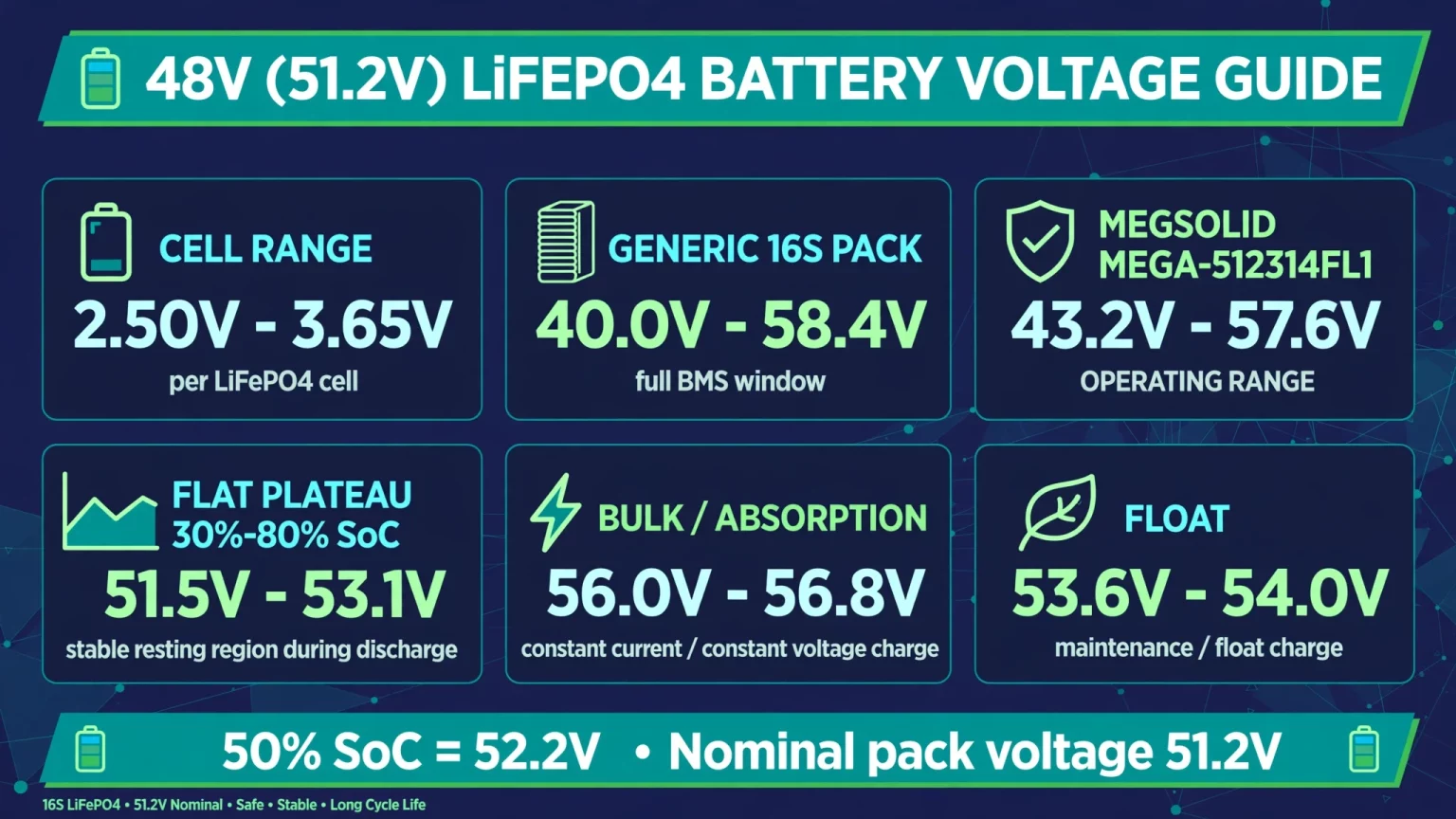
Standard nominal 3.2V LiFePO4 and semi-solid LFP cells have a LiFePO4 voltage range of 2.50V (0% SoC cut-off) to 3.65V (100% full charge). For a 16S 48V (51.2V nominal) solar battery bank, the operating voltage window is 40.0V to 58.4V, with a recommended daily solar bulk/absorption charge voltage of 56.0V to 56.8V (3.50V–3.55V per cell) and a float voltage of 53.6V to 54.0V (3.35V–3.38V per cell).
The tables below list resting State of Charge (SoC) voltages and manual MPPT charging setpoints for 3.2V cells, 12V (4S), 24V (8S), 15S (48.0V) and 16S (51.2V) battery banks.
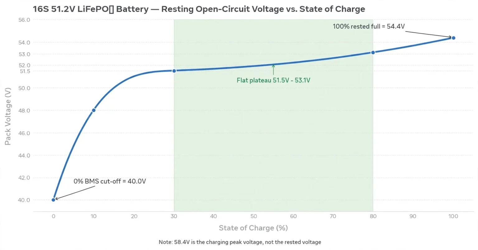
Complete LiFePO4 Voltage Range & State of Charge (SoC) Chart (3.2V / 12V / 24V / 48V / 51.2V)
Resting Open-Circuit Voltage vs. Voltage Under Load
The figures in Table 1 represent Resting Open-Circuit Voltage (OCV), measured after the battery has been disconnected from all charging sources and inverter loads for at least 30 minutes at 25°C (77°F).
When a battery is actively charging, terminal voltage reads 0.5V to 2.0V higher than resting OCV depending on charge current. Conversely, when powering heavy AC loads, terminal voltage drops below resting OCV due to internal cell impedance ($V_{\text{drop}} = I \times R_{\text{internal}}$).
15S (48.0V) vs. 16S (51.2V): Check Your Cell Count First
In the 48V solar and telecom market, two series configurations coexist under the "48V" label:
- 15S (15 cells in series, 48.0V nominal): Common in legacy telecom racks and certain brand-specific server-rack batteries. Maximum charge voltage is 54.75V ($3.65\text{V} \times 15$).
- 16S (16 cells in series, 51.2V nominal): The standard configuration for residential wall-mount, mobile and server-rack solar batteries, including MegSolid's 51.2V 314Ah battery series. Maximum datasheet voltage is 58.4V ($3.65\text{V} \times 16$).
Verify whether your pack is 15S or 16S on the nameplate before entering MPPT settings. Applying 16S charge voltages (56.0V–58.4V) to a 15S battery trips its BMS on Over-Voltage Protection (OVP), while applying 15S settings (52.5V–54.0V) to a 16S pack leaves it undercharged.
Table 1: Resting LiFePO4 & Semi-Solid State of Charge (SoC) Voltage Chart
| State of Charge (SoC) | Single Cell (3.2V) | 12V Pack (4S / 12.8V) | 24V Pack (8S / 25.6V) | 48V Pack (15S / 48.0V) | 48V Solar Pack (16S / 51.2V) | Operational Zone |
|---|---|---|---|---|---|---|
| 100% (Charging Peak) | 3.60V – 3.65V | 14.4V – 14.6V | 28.8V – 29.2V | 54.0V – 54.75V | 57.6V – 58.4V | Upper Knee (Cell Balancing) |
| 100% (Rested 30m) | 3.40V | 13.6V | 27.2V | 51.0V | 54.4V | True Rested Full |
| 90% SoC | 3.35V | 13.4V | 26.8V | 50.25V | 53.6V | Flat Plateau Start |
| 80% SoC | 3.32V | 13.28V | 26.56V | 49.8V | 53.1V | Optimal Daily Cycling |
| 70% SoC | 3.30V | 13.20V | 26.40V | 49.5V | 52.8V | Flat Plateau |
| 60% SoC | 3.27V | 13.08V | 26.16V | 49.05V | 52.3V | Flat Plateau |
| 50% SoC | 3.26V | 13.04V | 26.08V | 48.9V | 52.2V | Mid-Point Nominal |
| 40% SoC | 3.25V | 13.00V | 26.00V | 48.75V | 52.0V | Flat Plateau |
| 30% SoC | 3.22V | 12.88V | 25.76V | 48.3V | 51.5V | Flat Plateau End |
| 20% SoC | 3.20V | 12.80V | 25.60V | 48.0V | 51.2V | Recommended Grid/Gen Recharge |
| 10% SoC | 3.00V | 12.00V | 24.00V | 45.0V | 48.0V | Lower Knee (Rapid Drop) |
| 0% (BMS Cut-Off) | 2.50V | 10.00V | 20.00V | 37.5V | 40.0V | Hard BMS Under-Voltage Lockout |
Building or expanding a 16S home backup bank? Browse our 16S 51.2V residential solar battery banks rated from 16 kWh to 96 kWh.
Understanding the Flat Voltage Curve & Why Semi-Solid LFP Performs Better
The 30% to 80% Voltage Plateau
Unlike lead-acid or NMC lithium-ion batteries whose voltage slopes down from full to empty, lithium iron phosphate has a two-phase electrochemical reaction that produces a flat discharge curve between 30% and 80% SoC.
In the 16S (51.2V) column of Table 1, resting voltage between 80% SoC (53.1V) and 30% SoC (51.5V) changes by only 1.6V across the entire pack (0.10V per cell). Because a modest load current or ambient temperature shift moves terminal voltage by 0.5V to 1.0V, an inverter running in basic lead-acid voltage mode cannot read LiFePO4 state of charge reliably in the mid-SoC range. Accurate SoC tracking requires a Battery Management System (BMS) that counts Coulombs (integrating current over time, $\int I , dt$) and recalibrates when the pack reaches the upper voltage knee.
Standard Liquid LiFePO4 vs. 51.2V Hybrid Solid-State LFP
Conventional liquid-electrolyte LFP packs often run into two practical limitations: terminal voltage sag during high-inrush motor starts, and stricter indoor fire-safety requirements.
MegSolid's MEGA-512314FL1 51.2V 314Ah (16.07 kWh) Hybrid Solid-State Battery addresses both through its semi-solid LiFePO4 cell design:
- Low internal impedance ($\le 15\text{ m}\Omega$) and 200A continuous rating: Starting a 240V submersible well pump, air-conditioner compressor or workshop motor pulls a brief 3× to 6× inrush current from the inverter. On higher-resistance packs, that surge pulls terminal voltage below the inverter's low-voltage disconnect (for example, 48.0V) even at 30% SoC. With internal impedance at $\le 15\text{ m}\Omega$ and a 200A continuous charge/discharge rating (over 10 kW from one 16.07 kWh unit), the semi-solid cell interface keeps terminal voltage stable during motor starts.
- 8,000-cycle life and thermal stability: Immobilising the electrolyte in a semi-solid matrix prevents liquid leakage, reduces thermal runaway risk and supports 8,000 cycles at 80% DoD across a 43.2V to 57.6V operating window.
For residential and light-commercial installations requiring high surge capacity, see our full lineup of 48V (51.2V) semi-solid home energy storage batteries.
LiFePO4 Charge Voltage Settings: Bulk, Absorption, and Float Explained
Why Daily Solar Charging Targets 3.50V–3.55V/Cell Instead of 3.65V
Cell datasheets specify 3.65V per cell (58.4V on a 16S pack) as the upper voltage limit. In field installations, solar engineers program daily Bulk / Absorption lower, at 56.0V to 56.8V (3.50V–3.55V per cell), or up to the 57.6V (3.60V per cell) rating on the MEGA-512314FL1 datasheet.
Setting daily absorption at 3.50V–3.55V per cell avoids two common issues:
- Nuisance BMS Cell Over-Voltage Protection (COVP) trips: LiFePO4 cells reach roughly 99% state of charge by 3.45V–3.50V. Above 3.50V, cell voltage rises steeply. Because series cells never have identical internal resistance or state of charge, pushing a 16S pack to 58.4V often drives the highest cell past 3.65V while the remaining 15 cells sit near 3.58V. When that single cell crosses 3.65V, the BMS opens its charge MOSFETs, causing MPPT bus voltage to spike and triggering an inverter fault.
- Shortened balancing time and cathode stress: Holding absorption at 56.0V–56.8V for 15 to 30 minutes keeps all 16 cells inside the upper knee long enough for the BMS balancer to equalise cell voltages without tripping, supporting 6,000 to 8,000+ cycles.
Table 2: Recommended LiFePO4 Charge Voltage Settings (Manual Inverter / MPPT Mode)
| Charging Parameter | Single Cell (3.2V) | 12V (4S) System | 24V (8S) System | 48V (15S) System | 48V / 51.2V (16S) Solar System |
|---|---|---|---|---|---|
| Bulk / Absorption Voltage (Max Datasheet) | 3.65V | 14.6V | 29.2V | 54.7V | 57.6V – 58.4V |
| Bulk / Absorption (Optimal Daily Target) | 3.50V – 3.55V | 14.0V – 14.2V | 28.0V – 28.4V | 52.5V – 53.2V | 56.0V – 56.8V |
| Float Voltage | 3.35V – 3.38V | 13.4V – 13.5V | 26.8V – 27.0V | 50.2V – 50.7V | 53.6V – 54.0V |
| Equalization Voltage | DISABLE (Off) | DISABLE (0V) | DISABLE (0V) | DISABLE (0V) | DISABLE (Never Equalize LFP) |
| Absorption Time / Tail Current | 15–30 mins ($0.05\text{C}$) | 15–30 mins | 15–30 mins | 15–30 mins | 15–30 mins (or 2A–5A tail) |
| Temperature Compensation | $0\text{ mV}/^\circ\text{C}$ (Off) | $0\text{ mV}/^\circ\text{C}$ | $0\text{ mV}/^\circ\text{C}$ | $0\text{ mV}/^\circ\text{C}$ | $0\text{ mV}/^\circ\text{C}$ (Disable) |
| Recommended Low-Voltage Cut-Off (Inverter) | 3.00V – 3.10V | 12.0V – 12.4V | 24.0V – 24.8V | 45.0V – 46.5V | 48.0V – 49.6V (10%–15% SoC) |
Charging Batteries with Solar: Configuring Your 48V Hybrid Inverter & MPPT
The 2-Stage CC/CV Solar Charging Profile (+ Solar Float)
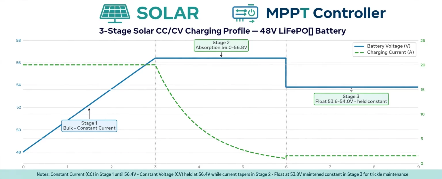
When charging batteries with solar through a 48V hybrid inverter or standalone MPPT controller, the charger runs a Constant Current / Constant Voltage (CC/CV) cycle:
- Stage 1 (Bulk / Constant Current): From morning through midday, the solar MPPT delivers maximum available current (0.2C to 0.5C, or 60A–150A for a 314Ah pack, up to the 200A rating of the MEGA-512314FL1) until terminal voltage reaches the absorption setpoint (56.0V–56.8V).
- Stage 2 (Absorption / Constant Voltage): The MPPT holds voltage at 56.0V–56.8V for 15 to 30 minutes while charge current tapers below $0.05\text{C}$ (or $0.01\text{C}$ on full-capacity tests), giving the BMS time to top-balance all 16 cells.
- Stage 3 (Float, 53.6V–54.0V): While disconnected LFP batteries in storage do not need float charging, an active solar inverter system requires a Float stage set at 53.6V–54.0V, right above the rested 100% plateau. Holding Float at 53.8V lets the solar MPPT supply household AC loads across the DC bus all afternoon while keeping the battery full for sunset, without micro-cycling the cells or holding them at 56.8V for hours.
Three Settings That Damage LiFePO4 Solar Banks
- Leaving Lead-Acid Equalization enabled: Lead-acid charge profiles boost voltage above 60V–62V to desulfate lead plates. On a 16S LiFePO4 battery, a 60V equalization pulse forces BMS over-voltage lockout and can damage MOSFETs if repeated. Set Equalization to Disabled / 0 minutes (or set Equalization Voltage equal to Bulk Voltage if the inverter firmware does not allow zero).
- Enabling Temperature Compensation: Lead-acid chargers raise charging voltage by $-3\text{ to }-5\text{ mV}/^\circ\text{C}/\text{cell}$ in cold weather. On a 48V lithium bank at $5^\circ\text{C}$, a lead-acid temperature sensor pushes charge voltage nearly 2V higher than programmed, causing COVP trips. Set Temperature Compensation to $0\text{ mV}/^\circ\text{C}$ and disconnect lead-acid temperature probes when using manual voltage mode.
- Charging below $0^\circ\text{C}$ ($32^\circ\text{F}$) without thermal protection: While MegSolid 51.2V semi-solid LFP batteries discharge down to $-20^\circ\text{C}$ ($-4^\circ\text{F}$), charging an LFP anode below $0^\circ\text{C}$ causes metallic lithium plating on the graphite surface and permanent capacity loss. MegSolid's BMS enforces a $0^\circ\text{C}$ to $45^\circ\text{C}$ charge window.
Closed-Loop vs. Open-Loop: Why Smart 51.2V Batteries Eliminate Voltage Guessing
Programming Bulk, Absorption, Float and Low-Voltage Cut-Off manually in "User-Defined (USE) Open-Loop Mode" works for older inverters, but it has two drawbacks: the inverter relies on terminal voltage to guess SoC, and it cannot adjust charge current if a single cell warms up or drifts out of balance.
Modern smart 51.2V home batteries with CANbus and RS485 auto-configuration operate in closed-loop communication mode:
- Connect a standard RJ45 communication cable between the battery's CAN or RS485 port and your hybrid inverter (including MegSolid's own 3–6 kW Single-Phase Hybrid Inverter and 30–50 kW Three-Phase Hybrid Inverter, as well as mainstream protocols used by Deye, Victron, Growatt, Sol-Ark, Luxpower and GoodWe).
- The battery BMS acts as the master controller, broadcasting real-time Coulomb-counted SoC (0%–100%), State of Health (SoH), exact charge voltage limits and charge/discharge current limits to the inverter every second.
MegSolid 51.2V (16S) Flagship Battery Lineup
| Model | Chemistry & Format | Rated Capacity & Energy | Operating Voltage & Current | Cycle Life & Parallel Scalability |
|---|---|---|---|---|
| MEGA-512314FL1 | 51.2V Semi-Solid LiFePO4 (Sheet-Metal Stationary Pack, IP21/IP65) | 314Ah / 16.07 kWh | 43.2V – 57.6V · 200A charge / 200A discharge ($\le 15\text{ m}\Omega$) | 8,000 cycles (80% DoD) · RS485 / RS232 / CAN + Optional Wi-Fi/BT |
| MEGA-512314 Mobile | 51.2V Solid LFP (Wheeled Floor-Standing Pack, IP21) | 314Ah / 16.076 kWh | 40.0V – 58.4V · 200A charge / 200A discharge | $\ge 6,000$ cycles · Parallel up to 6 units (96.4 kWh) · RS485 / CAN / RS232 |
FAQ
Do semi-solid 48V batteries use the same charging voltages as standard LiFePO4?
They share the LFP nominal cell-voltage basis, but the exact charge ceiling and operating window remain model-specific. The MEG-Solid-512314FL1 is specified with a 57.6V charging voltage and a 43.2V–57.6V working range. Do not assume every 16S pack accepts 58.4V.
How can I tell whether my 48V battery is 15S or 16S?
Check the battery nameplate and controlled datasheet for the series-cell count and nominal voltage. A 15S LFP pack is nominally 48.0V; a 16S pack is nominally 51.2V. Never choose MPPT settings from the informal “48V” label alone.
Why is voltage a poor SoC indicator between 30% and 80%?
LFP discharge voltage has a relatively flat plateau through much of the middle SoC range. Load current and temperature also shift terminal voltage. A BMS using current integration and cell monitoring provides a more reliable SoC estimate than a basic inverter voltage table.
What bulk or absorption voltage should I use for a 16S 51.2V battery?
The guide gives 56.0V–56.8V as a typical daily target for a generic 16S LFP setup. The MEG-Solid-512314FL1 product specification lists 57.6V charging voltage. Confirm the approved setpoint and absorption duration against the exact battery and inverter manuals before commissioning.
What float voltage should I use for a 48V LiFePO4 solar battery?
The guide lists 53.6V–54.0V as a typical 16S system float range. Some battery and inverter combinations use different float logic or allow float to be disabled. Follow the battery maker’s approved profile and avoid holding the pack at a high absorption voltage unnecessarily.
Which lead-acid charger functions should be disabled for LiFePO4?
Disable lead-acid equalization and do not apply a lead-acid temperature-compensation curve unless the battery maker explicitly requires it. In manual mode, verify zero temperature compensation and confirm the controller cannot issue a high-voltage equalization pulse.
Can I charge a MegSolid 51.2V semi-solid battery below 0°C?
No. The MEG-Solid-512314FL1 specification lists a 0°C–45°C charging temperature range. Its listed discharge range is −20°C to 60°C. Charging and discharging limits are different and must not be interchanged.
What should a South African installer verify before setting a 48V LiFePO4 inverter?
Confirm whether the battery is 15S or 16S, use its model-specific voltage limits, verify CAN or RS485 compatibility where closed-loop control is required, and check the applicable local installation and utility requirements. This guide does not define a South Africa-specific voltage profile.
What should an Australian buyer check when matching a 51.2V battery to a solar inverter?
Verify the battery’s approved charge voltage, inverter battery-voltage window, maximum charge current, BMS communication protocol and any required local electrical approvals. The country does not change the pack’s cell count or manufacturer voltage limits.
Do Saudi Arabian high temperatures change the 48V LiFePO4 voltage chart?
The nominal cell-voltage basis does not change, but operating temperature can affect available power, charging permission and battery life. Check the exact product temperature limits, installation conditions and inverter derating requirements. The guide does not provide a Saudi-specific voltage setting.
Get Your 48V Solar Battery Spec Sheet & Inverter Setup Guide
Need help matching a 51.2V semi-solid battery bank to your solar inverter or sizing a residential or light-commercial project? Contact MegSolid's technical team to request our 51.2V 314Ah Hybrid Solid-State Battery datasheets, inverter CAN/RS485 pinout guide and wholesale pricing, or view our full range of solid-state energy storage systems.