
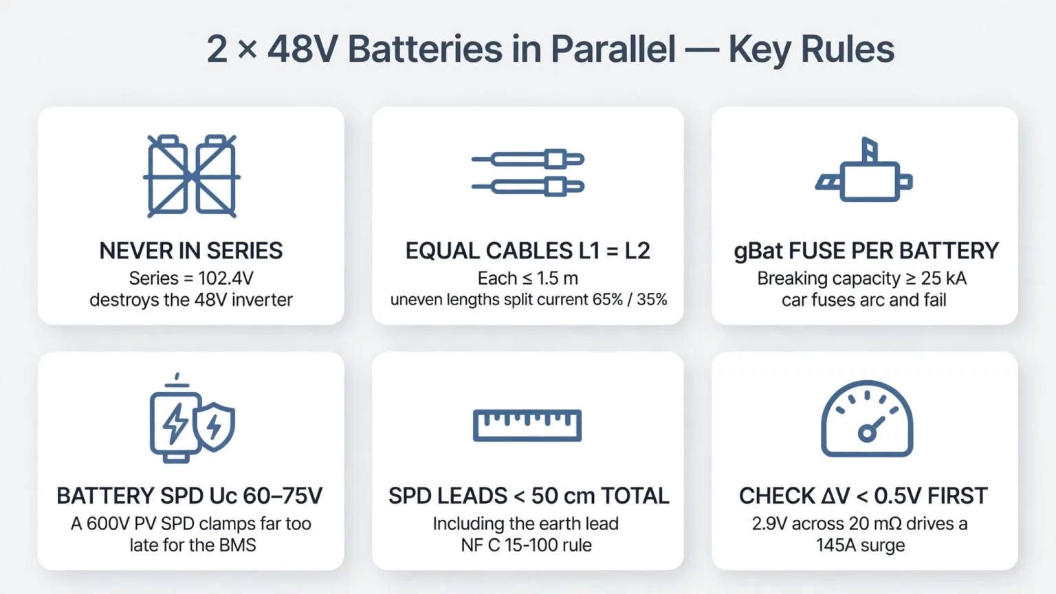
Designing a **wiring diagram for two 48V (51.2V nominal) lithium batteries in parallel with a DC surge protection device (DC SPD)** for Francophone solar-plus-storage installations requires wiring both battery packs to a common copper DC busbar using branch cables of identical length (L₁ = L₂) and cross-section. Never connect two 48V lithium packs in series on a 48V hybrid inverter: series connection doubles the nominal voltage to 102.4V DC (reaching 115.2V DC at a 57.6V charging setpoint) and will damage the inverter's low-voltage DC input stage.
When preparing a residential or light-commercial installation in France or regions referencing French electrical standards, such as **NF C 15-100**, the **XP C 15-712-3 (formerly UTE C 15-712-3)** guide for grid-connected PV systems with battery storage, and CONSUEL inspection procedures (where form selection, such as SC-144C or equivalent, must be verified against the current project scope and grid-connection architecture), four core DC protection elements are engineered between the battery bank and the hybrid inverter:
- Individual overcurrent protection on each battery branch using a battery-rated DC fuse (`gBat` per IEC 60269-7) or a non-polarized DC molded-case circuit breaker (MCCB per IEC 60947-2) whose short-circuit breaking capacity (Icu) exceeds the calculated prospective short-circuit current (Icc) at that point;
- Positive and negative tinned copper DC busbars sized for the maximum continuous current allowed by the inverter and battery system;
- Where required by the site lightning risk assessment or installation standard, a dedicated Very Low Voltage (VLV / TBT) Type 2 DC Surge Protection Device coordinated with the 48V battery bus maximum operating voltage (distinct from the high-voltage PV DC surge protector installed on the solar MPPT strings);
- One main omnipolar (2-pole, + and -) DC fuse-disconnector or breaker providing simultaneous load-break isolation of both poles between the DC busbar and the hybrid inverter.
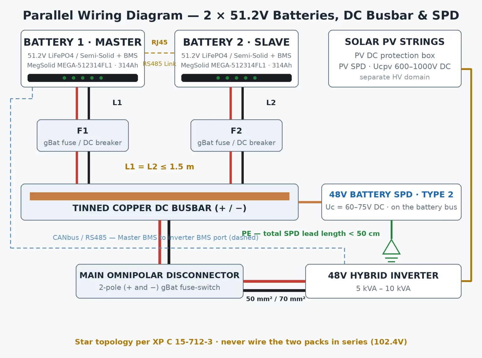
Complete Parallel Wiring Diagram: 2 × 48V (51.2V) Lithium Batteries + DC Protection Box
The schematic below illustrates the star-topology parallel connection of two 48V (51.2V) lithium batteries onto a common DC busbar, the BMS communication link (`RS485` / `CAN` / `RS232`), and the physical separation between the solar PV MPPT DC protection box and the low-voltage 48V battery DC protection box.
Engineering Rule #1: Equalizing Branch Cable Lengths (L₁ = L₂)
Lithium iron phosphate (LiFePO4) and semi-solid-state 51.2V batteries operate with much lower internal resistance than lead-acid blocks. On the stationary MegSolid MEG-Solid-512314FL1 51.2V 314Ah (16.07 kWh) Semi-Solid Battery, internal impedance is specified at ≤ 15 mΩ.
When battery internal impedance is that low, small differences in external branch cable resistance alter how charge and discharge currents divide between parallel packs. If an installer wires Battery 1 to the DC busbar with 0.75 m of 35 mm² copper cable (Rloop,1 ≈ 0.79 mΩ) and wires Battery 2 with 1.50 m of the same cable (Rloop,2 ≈ 1.58 mΩ), the shorter branch presents lower total loop impedance. Under a 120A inverter load, Battery 1 will carry a disproportionately higher share of current than Battery 2, causing uneven cell cycling and premature BMS current-limit trips on the first pack.
To maintain balanced current sharing across parallel 51.2V battery branches:
- Use the exact same conductor cross-section and fine-stranded flexible copper class (Class 5 copper per IEC 60228, such as H07RN-F, H1Z2Z2-K, or certified battery cable) on both battery branches;
- Cut the positive and negative leads for Battery 1 and Battery 2 to the exact same physical length (L₁ = L₂ ≤ 1.50 m), even when one battery sits closer to the busbar enclosure;
- Crimp tin-plated tubular copper lugs using a calibrated hydraulic crimper and terminate each battery branch onto a common copper DC busbar rather than daisy-chaining power cables from one battery terminal to the next.
Coordinating DC Surge Protection (DC SPD) on a 48V Battery System
Why Solar PV DC SPDs (600V/1,000V) Cannot Protect a 48V Battery Bus
One frequent design error in hybrid solar installations is placing a high-voltage solar PV DC surge arrester onto the 48V battery busbar.
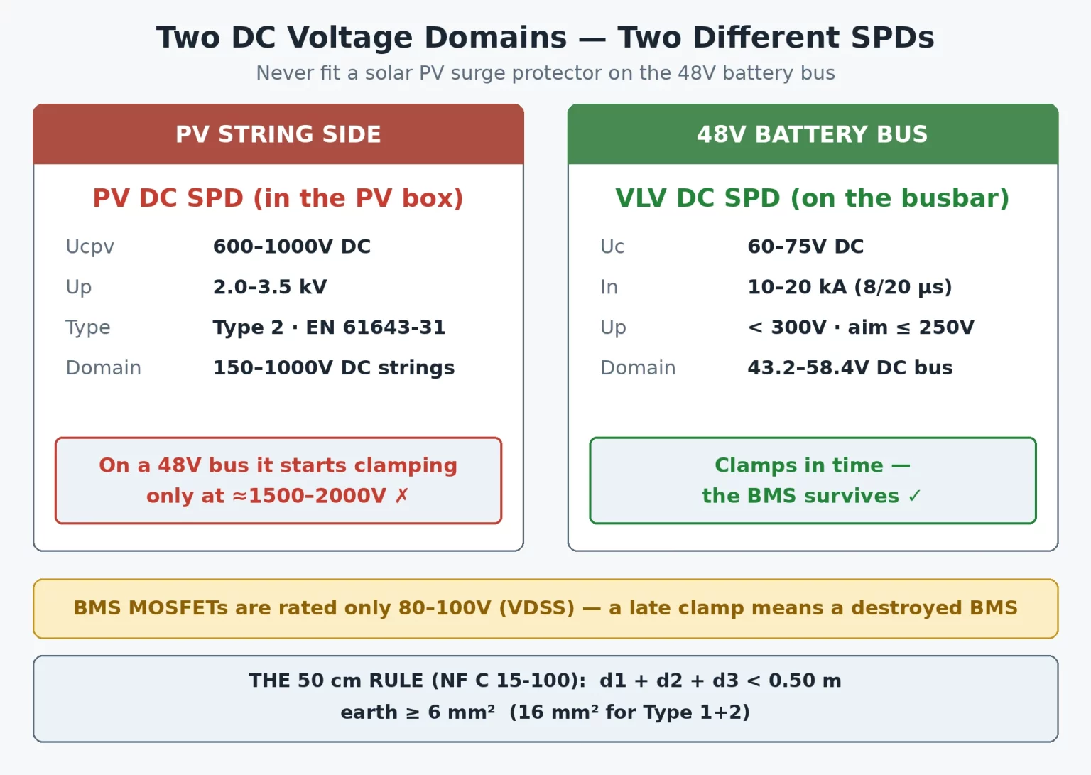
Every hybrid solar-plus-storage plant operates two distinct DC voltage domains that require separate surge coordination. The wider PV-to-battery architecture also affects where conversion and protection equipment sits; see MegSolid’s guide to AC-coupled vs. DC-coupled solar battery storage before finalizing the system layout:
- Solar PV MPPT String Side (150V to 1,000V DC): The solar string protection box (*Coffret DC PV*) uses a PV-specific Type 2 DC SPD (per EN 61643-31) with a maximum continuous operating voltage Ucpv of 600V DC or 1,000V DC and a voltage protection level Up typically between 2.0 kV and 3.5 kV.
- Low-Voltage 48V Battery Busbar Side: Stationary and mobile 51.2V LiFePO4 / semi-solid batteries operate at much lower voltages. Specifically, the `MEG-Solid-512314FL1` operates across 43.2V to 57.6V DC (with a 57.6V charging voltage), while the mobile MegSolid MG 512314 51.2V 314Ah (16.076 kWh) Battery operates across 40V to 58.4V DC (with a 57.6V standard charging voltage). Low-voltage 48V BMS switching stages typically rely on power semiconductors (often in the 80V to 100V breakdown class, depending on BMS design) and low-voltage inverter DC/DC input components. Because a 600V solar SPD does not clamp until a transient exceeds 1,500V to 2,000V, it remains inactive during low-voltage surges that are already high enough to damage a 48V BMS or inverter input board.
- Selecting and Coordinating a 48V Battery Bus DC SPD: When a DC SPD is installed on the 48V busbar, engineers select a dedicated Very Low Voltage (VLV / TBT) DC SPD whose maximum continuous operating voltage (Uc) exceeds the maximum charging/operating voltage of the battery bank (>57.6V DC for `MEG-Solid-512314FL1` or >58.4V DC for `MG 512314`, commonly Uc = 60V DC or 75V DC depending on the SPD manufacturer's product series) while offering a low residual voltage protection level (Up, typically <300V) coordinated with the downstream equipment's impulse withstand rating (Uw).
Lead Length Control and the NF C 15-100 "50 cm" Connection Principle
During a fast-rising surge current (di/dt), lead inductance creates an additional voltage drop (Δ U = L · di/dt) across the wires connecting the SPD to the active busbar and to the earthing system. If those connecting leads are excessive, the inductive voltage drop adds to the SPD's clamping voltage Up and raises the actual voltage seen by the battery terminals.
Under NF C 15-100 surge protection installation rules, installers must keep the SPD connecting leads between the active conductors/busbar, the manufacturer-specified backup disconnector/fuse, and the enclosure's equipotential earthing terminal as short and straight as possible, targeting a connection path under 50 cm (or applying "V-wiring" / local equipotential bonding to the equipment chassis as detailed in the applicable NF C 15-100 clause when physical layout prevents a <50 cm path). Always verify the exact conductor cross-section (6 mm² or 16 mm² copper depending on Type 2 vs. Type 1+2 classification) against the SPD manufacturer's installation sheet and current national code edition.
When Is a DC SPD Required on the 48V Storage Circuit?
Installing a DC SPD on a 48V battery bus is not an unconditional requirement for every indoor short-coupled cabinet; rather, under French PV-storage design rules (such as XP C 15-712-3 / UTE C 15-712-3), the requirement is determined by site conditions:
- Whether the building is fitted with an external lightning protection system (*paratonnerre*);
- Whether the DC battery conductors are routed outdoors or between two separate buildings (such as a battery bank installed in a detached garage or technical shed);
- Whether the DC cable run length between the battery bank and the hybrid inverter exceeds the critical length threshold defined by the standard and local keraunic / flash density (N_g). Even where not strictly mandatory for short indoor runs, electrical design offices frequently include a coordinated VLV Type 2 DC SPD inside the 48V DC protection box for added surge immunity.
Send the battery model, inverter model, DC cable route and site lightning-protection details to MegSolid. The engineering team can review the proposed 48V protection arrangement and identify which model-specific documents are needed before installation.
Sizing Table: Cable Cross-Sections, gBat DC Fuses, and DC Breakers
Coordinating Short-Circuit Breaking Capacity (Icu) vs. Prospective Fault Current (Icc)
Low-voltage automotive fuse holders (such as standard 32V or 58V ANL fuses with interrupting ratings of only 1 kA to 2 kA) are frequently flagged during professional electrical audits on stationary lithium battery banks. Because lithium cells have very low internal resistance, a bolted short circuit across a parallel 51.2V busbar can generate a prospective short-circuit current (Icc) of several kiloamperes depending on the number of parallel packs, internal cell/BMS impedance, and cable length.
In accordance with XP C 15-712-3 and IEC protection coordination principles, overcurrent devices on the battery DC circuit must be selected by calculating the actual prospective short-circuit current (Icc) at the installation point and choosing either:
- Battery-rated industrial DC fuses marked `gBat` (compliant with IEC 60269-7, whose breaking capacity Icu, often 25 kA to 50 kA depending on the NH fuse model, exceeds the calculated Icc) housed in a load-break fuse-disconnector; or
- Non-polarized DC Molded-Case Circuit Breakers (DC MCCBs per IEC 60947-2) certified for bidirectional DC operation with Icu ≥ Icc at the system's maximum DC voltage.
Table 1: Reference DC Cable & Protection Sizing Examples for 2 × 48V (51.2V) Batteries in Parallel
*Note: The table below provides engineering reference examples for two common inverter power tiers. Final cable gauges, fuse ratings, and breaking capacities (Icu) must be calculated by a qualified electrical engineer according to actual route lengths, ambient temperature, prospective fault current (Icc), and the specific inverter's maximum battery current.*
| Circuit Section / Protection Component | Scenario 1: 2 × 51.2V Batteries with 5 kW–6 kW Single-Phase Hybrid Inverter (100A–120A Max Inverter DC Current) | Scenario 2: 2 × MG 512314 (51.2V 314Ah Mobile Packs) with 8–10 kVA 48V Hybrid Inverter (200A Max Inverter DC Current) | Engineering & Code Design Basis |
|---|---|---|---|
| Individual Battery Branch Cables (Battery 1 & 2 to DC Busbar) | 35 mm² flexible copper (H07RN-F / H1Z2Z2-K), equal length L₁ = L₂ ≤ 1.5 m | 50 mm² flexible copper (H07RN-F / H1Z2Z2-K), equal length L₁ = L₂ ≤ 1.5 m | Keeps voltage drop < 1% and ensures symmetrical current sharing between branches |
| Individual Protection per Battery Branch | NH00 `gBat` Fuse 100A–125A or Non-Polarized DC MCCB 125A (Icu > Icc) | NH1 `gBat` Fuse 200A or Non-Polarized DC MCCB 200A (Icu > Icc) | Protects each individual battery branch cable and isolates a faulted pack |
| Common DC Busbar (+ and – Bars) | Tinned copper busbar rated ≥ 250A inside IP2X insulated enclosure | Tinned copper busbar rated ≥ 400A inside IP2X insulated enclosure | Symmetrical star connection point with IP2X protection against direct contact |
| Main Inverter Feeder Cable (DC Busbar to 48V Inverter) | 50 mm² flexible copper (L ≤ 2.0 m) | 70 mm² or 95 mm² flexible copper (L ≤ 2.0 m) | Sized for the inverter’s maximum continuous DC current plus safety margin |
| Main Omnipolar DC Fuse-Disconnector | 2-Pole NH1 Fuse-Switch with 125A–160A `gBat` fuses (or 2-Pole DC MCCB) | 2-Pole NH1/NH2 Fuse-Switch with 250A `gBat` fuses (or 2-Pole DC MCCB) | Simultaneous omnipolar (+ and -) emergency load-break isolation |
| 48V Battery Bus DC Surge Protector (When Required) | Type 2 VLV DC SPD (Uc > 58.4V DC, e.g., 60V–75V DC, Up coordinated with BMS/Inverter) | Type 2 VLV DC SPD (Uc > 58.4V DC, e.g., 60V–75V DC, Up coordinated with BMS/Inverter) | Installed per NF C 15-100 lead-length rules with manufacturer-specified backup fuse |
Step-by-Step Commissioning Procedure: Paralleling 2 × 48V (51.2V) Batteries Safely
Step 1: Pre-Paralleling Voltage Balancing (Engineering Precaution: ΔV < 0.5V)
As a general field engineering precaution, installers should never close two 48V lithium batteries onto a common DC busbar when they sit at widely different states of charge. If one pack is fully charged while the second pack is partially depleted, the voltage differential across the low loop impedance of the busbar will drive a large cross-charging current between the two batteries, risking fuse operation or BMS overcurrent trips.
Before closing both branch switches onto the common busbar:
- Charge each battery pack individually to full state of charge using a compatible hybrid inverter or LiFePO4 charger configured to the manufacturer's specified charging voltage. For both the MegSolid `MEG-Solid-512314FL1` and `MG 512314`, the official charging voltage is 57.6V (while ensuring the charging current setting never exceeds the lower of the battery BMS limit and the inverter/charger rating);
- Allow both packs to rest open-circuit and verify with a calibrated digital multimeter that the terminal voltage difference between Battery 1 and Battery 2 is minimal (typically controlled to ΔV < 0.5V in field commissioning practice) before paralleling.
Step 2: BMS Communication Interfaces (`RS485` / `CAN` / `RS232`) and Inverter Matching
Both the stationary `MEG-Solid-512314FL1` and the mobile `MG 512314` provide `RS485`, `RS232`, and `CAN` communication interfaces (with optional Bluetooth/Wi-Fi on the `MEG-Solid-512314FL1`). Because pin assignments, DIP switch addressing, and multi-pack communication topologies depend on the exact BMS hardware revision and inverter brand, installers must always wire communication cables strictly according to the official user manual supplied with the units rather than assuming generic RJ45 port labels. For a broader model-level checklist covering battery voltage windows, inverter current limits and BMS interface verification, consult MegSolid’s battery–inverter compatibility and interface guide.
When selecting a MegSolid hybrid inverter for a 51.2V battery system, pay close attention to voltage and current compatibility across product families:
- Compatible 48V Single-Phase Inverter (`G2S-C` Series, 3 kW–6 kW): The MegSolid G2S-C 3–6 kW Single-Phase Energy Storage Inverter operates over a `40V–58V DC` battery voltage range, making it voltage-compatible with 51.2V batteries (`43.2V–57.6V` on the `MEG-Solid-512314FL1`). However, engineers must match the system design to the inverter's maximum battery charge/discharge current rating by model:
- — `3 kW` G2S-C model: 60A max charge / discharge current
- — `4 kW` G2S-C model: 80A max charge / discharge current
- — `5 kW` G2S-C model: 100A max charge / discharge current
- — `6 kW` G2S-C model: 120A max charge / discharge current Consequently, even though a single 51.2V 314Ah battery is rated for up to 200A continuous discharge, a 5 kW or 6 kW G2S-C inverter will cap total battery current at 100A or 120A respectively.
- Incompatible High-Voltage Three-Phase Inverters (`R30KH3 / R40KH3 / R50KH3`, 30 kW–50 kW): MegSolid's three-phase R30KH3 (30 kW), R40KH3 (40 kW), and R50KH3 (50 kW) hybrid inverters require a 150V–800V DC high-voltage battery bank and cannot be used with 51.2V low-voltage battery packs.
Step 3: Avoiding Capacitive Inrush Arcs During Power-Up
Hybrid 48V inverters incorporate high-capacitance DC link capacitors across their battery input terminals. Closing a mechanical knife switch from an already-energized 51.2V battery bank onto an uncharged inverter DC bus causes a high-current capacitive inrush spike that can pit switch contacts or trigger BMS short-circuit protection.
To commission the DC bus without arcing:
- With the batteries turned OFF, verify positive (+) and negative (-) polarity at every battery terminal, busbar stud, fuse holder, and inverter terminal using a multimeter;
- Close the individual branch fuse-disconnectors (F1 and F2) and close the main omnipolar DC fuse-disconnector feeding the inverter while the battery packs are still switched OFF;
- Power on the batteries according to the sequence in the MegSolid operating manual so that the inverter's DC bus capacitors are energized safely before full load current is applied.
Choosing Between MegSolid's 51.2V 314Ah Battery Models: `MEGA-512314FL1` vs. `MEGA 512314`
To help solar installers, electrical engineering firms, and system integrators select the right 51.2V storage unit from MegSolid without mixing specifications across product lines, here is the exact distinction between our stationary semi-solid battery and our wheeled mobile battery:
- `MEG-Solid-512314FL1` (Stationary 51.2V 314Ah / 16.07 kWh Semi-Solid Residential Battery): Our MEG-Solid-512314FL1 51.2V 314Ah Hybrid Solid-State Battery is built with semi-solid LiFePO4 battery technology for enhanced thermal stability in residential and commercial indoor spaces. Key confirmed parameters include:
- — Rated Energy & Voltage: 16.07 kWh (51.2V, 314Ah), operating voltage range 43.2V–57.6V, charging voltage 57.6V;
- — Current & Impedance: Up to 200A max charging and continuous discharging current for a single unit, with internal impedance ≤ 15 mΩ;
- — Cycle Life & Certifications: 8,000 cycles (at 80% DoD, 0.5C/0.5C, 25°C), IP21/IP65 enclosure options, `RS485 / RS232 / CAN` interfaces, and `UL / CE / UN38.3` listings on the official specification sheet. *(Note: Multi-unit parallel configurations and specific protocol files for `MEG-Solid-512314FL1` should be confirmed directly with MegSolid engineering prior to project design.)*
- `MG 512314` (Wheeled 51.2V 314Ah / 16.076 kWh Mobile Energy Storage Battery, Up to 6 Units in Parallel): For installations specifically requiring verified multi-pack parallel expansion, our floor-standing wheeled MG 512314 51.2V 314Ah Mobile Energy Storage Battery provides:
- — Rated Energy & Voltage: 16.076 kWh (51.2V, 314Ah), working voltage range 40V–58.4V, standard charging voltage 57.6V;
- — Verified Parallel Expansion: Officially confirmed support for up to 6 units in parallel (up to 96.4 kWh total energy) with `RS485 / CAN / RS232` interfaces and ≥ 6,000 cycles. While two `MG 512314` packs rated at 200A each represent a theoretical combined current capability of 400A, actual continuous system current and power output are governed by the connected inverter's DC current limit, BMS settings, and external protection sizing.
Compare full specifications on our 48V (51.2V) Residential Semi-Solid & LiFePO4 Solar Batteries page →
FAQ
Why must the two battery branch cables have equal lengths?
Unequal cable resistance changes the current shared by the parallel batteries. Use the same conductor material, cross-section and positive/negative cable lengths on both branches, and connect them to a common busbar. The article uses equal branch lengths of up to 1.5m as a design target; the final length and cross-section still depend on the installation calculation.
Can two 51.2V batteries be connected in series to increase capacity?
No. Series connection raises nominal voltage to 102.4V, which is outside the 40–58V battery-input range of the MegSolid G2S-C low-voltage inverter. A 48V-class inverter must receive a correctly configured low-voltage battery bank. Do not connect the packs in series unless the complete system is specifically designed and rated for the resulting voltage.
Which DC surge protector should be installed on a 48V battery bus?
Use a dedicated low-voltage DC SPD selected for the battery bus, not a PV-string SPD. Its maximum continuous operating voltage (Uc) must exceed the battery system's maximum normal operating voltage, while its protection level (Up) must be coordinated with the inverter and BMS withstand ratings. The MEG-Solid-512314FL1 lists a 57.6V charging voltage and the MG 512314 lists a 58.4V upper battery-voltage limit; the SPD manufacturer must confirm the suitable device and backup protection.
Why can a 600V or 1,000V PV SPD not protect a 48V battery bus?
A PV SPD is designed for a much higher DC voltage domain. Its clamping level can be far above the withstand capability of low-voltage battery electronics, so it may not limit a transient soon enough to protect the 48V BMS or inverter input. PV-string and battery-bus SPDs must be selected and coordinated separately.
Is a battery-side DC SPD mandatory in every 48V installation?
No single rule in this article makes a battery-side SPD mandatory for every installation. The decision depends on the applicable installation standard, lightning-risk assessment, external lightning protection, cable routing between buildings, outdoor cable exposure and the battery-to-inverter cable run. Confirm the requirement for the actual site and current code edition.
How should the breaking capacity of a battery fuse or DC breaker be selected?
Calculate the prospective short-circuit current at the protective device and select a device whose DC breaking capacity is at least that value at the system voltage. Battery-rated gBat fuses or DC breakers certified for the actual DC application may be used. Do not assume an automotive fuse with a low interrupting rating is suitable for a stationary lithium battery bank.
Does the MEG-Solid-512314FL1 support parallel expansion, and how should BMS communication be checked?
The public MegSolid reference lists RS485, RS232 and CAN interfaces for the MEG-Solid-512314FL1 but does not specify a confirmed maximum number of parallel units. The MG 512314 page lists parallel operation of up to six units. Do not transfer the MG 512314 parallel limit to the stationary model. Obtain the exact model's BMS manual, approved communication topology and written parallel-operation confirmation before installation.
Which French standards and inspection requirements should be checked for a 48V battery installation?
For a project in France, review the applicable edition and scope of NF C 15-100 and XP C 15-712-3 for the PV-storage architecture, together with the relevant CONSUEL inspection requirements. The correct inspection form depends on the installation and connection arrangement; verify it with the project designer or inspection body rather than assuming one form applies to every system.
Can XP C 15-712-3 be used as the sole compliance basis for a battery installation in Belgium or Switzerland?
No. A French guide should not automatically be treated as the complete compliance basis in another country. The project team must identify the applicable national electrical installation rules, grid-connection requirements and inspection process for the actual site. The cable-balancing, branch-protection and SPD-coordination principles in this article remain useful engineering checks, but local compliance must be confirmed separately.
What should EPCs check when installing 48V battery systems in Francophone African markets?
Confirm the electrical code and approval authority applicable in the project country; French standards apply only where adopted by local regulation, the utility or the project specification. Also assess site temperature, dust, lightning exposure, outdoor cable routes, earthing, enclosure protection and access to qualified commissioning support. Require model-specific battery and inverter documents before finalizing protection ratings.
Request Official Datasheets & Engineering Support from MegSolid
Planning a residential or commercial 51.2V energy storage installation and need to verify inverter compatibility, parallel communication protocols, or certification documentation (`UL / CE / UN38.3`) for your project? MegSolid's engineering team for official product manuals and distributor quotes, or explore our complete portfolio of solid-state energy storage systems.