
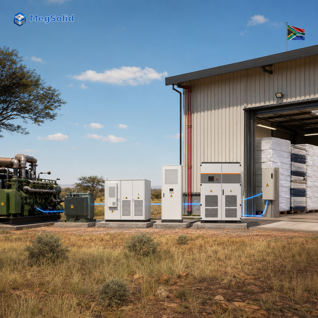
An unstable community gas-turbine supply raises import during mattress-production ramps, interrupts selected production branches and leaves PLCs and controls without approved safe-stop time. MegSolid configures a commercial battery storage system around the factory event that creates this loss: hold the meter limit, keep the approved branch energised and complete the safe-stop sequence with a protected SOC reserve.
| Core factory value | System result | Evidence used to prove it |
|---|---|---|
| Control high import | PCS supplies the measured kW/kVA gap at the factory-meter boundary | 15-minute meter record and approved import limit |
| Protect production continuity | Battery energy supports the named branch through the approved source event | Critical-load list, source event record and branch test |
| Protect product and equipment | EMS retains energy for the stated PLC and ordered-load safe-stop sequence | Signed safe-stop sequence and SOC record |
| Prepare the next event | EMS recharges within verified source headroom | Source limit, factory load and recovery-window record |
System architecture at the factory AC boundary
| Equipment layer | Function during the production event | Decision it answers |
|---|---|---|
| Factory meter and switchboard | Measures import and sends the controlled value to EMS | What import level is the factory protecting? |
| PCS | Delivers the approved active and apparent power | What kW and kVA gap must the system carry? |
| Battery system | Holds event energy and the continuity reserve | How long must the selected duty run? |
| EMS | Sets peak control, source-loss, safe-stop and recovery states | Which duty has priority at each stage? |
Scope of Work
| Work package | MegSolid scope | Factory and local EPC scope | Acceptance output |
|---|---|---|---|
| BESS and PCS product path | BESS model direction, PCS route, BMS/EMS interface and product documentation | Confirm electrical connection point, location and operating objective | Approved product path and system boundary |
| Meter and source interface | Input requirements for control logic | Meter boundary, community-source data, transformer, switchgear and protection coordination | Controlled single-line diagram |
| Site delivery | Equipment supply within the agreed quotation scope | Cable route, civil work, lifting, installation, grounding, permits and local approvals | Installed site scope and responsibility matrix |
| Commissioning | Factory documentation and agreed test input | Field installation, source interface, test witnessing and sign-off | Meter, source, safe-stop and recharge records |
Fix the Operating Result Before Sizing the BESS
The factory does not need one broad battery objective. It needs one operating result for each loss event. The written result tells the project team what the PCS must deliver, how much battery energy the event consumes and which duty keeps priority.
| Production loss | Approved operating result | BESS action | Factory decision |
|---|---|---|---|
| Demand rises during cutting or compression ramp | Keep import at or below the approved meter target for the recorded interval | PCS discharges only for the import gap | Set the meter limit and tariff interval |
| Community gas-turbine source enters the defined loss state | Keep cutting, compression and controls branch supplied through the approved event | EMS enters continuity state and holds the SOC reserve | Approve the critical-load branch and event duration |
| Process must stop in order | Keep PLCs, controls and ordered equipment supplied until the sequence completes | EMS runs the safe-stop priority table | Approve the safe-stop list and duration |
| Source returns | Restore the operating reserve before the next event | Charge inside verified source headroom | Approve the recovery window |
Factory data that supports each result
- Meter-control duty: interval import data, maximum-demand record, tariff interval, target import limit and production-ramp schedule.
- Continuity duty: selected feeder list, source-loss record, firm source contribution, branch kW/kVA and required operating duration.
- Safe-stop duty: PLC sequence, ordered-load list, controls demand, conveyor/motor order and approved completion time.
- Recovery duty: normal factory demand, source kW available for charging and time before the next planned ramp or source event.
The C&I peak-shaving ROI analysis provides the financial review route for the meter-control event. The factory production record and electrical event record establish the continuity and safe-stop value boundary.
Define the Meter, Critical-Load and Source Boundaries
The factory needs three named boundaries on one controlled single-line diagram. The meter boundary governs the cost event. The critical-load panel governs the production event. The source boundary governs the continuity and recharge calculation.
| Boundary | Data the project team records | BESS/EMS action | Local EPC delivery |
|---|---|---|---|
| Factory meter or PCC | kW, kVA, power factor, tariff interval and approved import limit | EMS receives the meter value and sends the PCS setpoint | Meter interface, CT/PT route, switchboard connection and commissioning record |
| Critical-load panel | Selected feeders, branch demand, PLC/controls load and load priority | EMS supplies only the approved branch during continuity and safe-stop states | Feeder segregation, ATS/protection coordination and field wiring |
| Community gas-turbine interface | Firm source contribution, voltage/frequency status, loss signal and return sequence | EMS removes unvalidated source contribution from the duty and applies the approved source state | Incomer interface, protection review, source controller ownership and test coordination |
Scope boundary for local PV
PV modules, mounting and PV installation are outside the MegSolid BESS supply scope. Local procurement supplies the PV package. The local EPC defines the electrical integration, meter position and operating priority. The energy storage inverter and PCS range then coordinates the approved factory signals.
Select PCS Power From the Recorded AC Gap
PCS power is selected from the power gap at the exact operating moment. It does not come from the battery kWh label. The factory records active power and apparent power during the production event, then the electrical design sets the PCS and protection envelope.
| Sizing line | Calculation | Engineering meaning | Scope owner |
|---|---|---|---|
| Meter-control active power | Recorded factory demand − approved meter limit | PCS kW required to hold the import target | Factory supplies meter record; MegSolid maps product route; local EPC reviews connection |
| Continuity active power | Selected critical-load demand − firm source contribution | PCS kW required to keep the branch supplied | Factory approves branch; local EPC validates source contribution and feeders |
| Apparent power | Measured kW, kVA, power factor and motor/VFD behaviour | PCS, transformer and protection envelope | Local EPC and engineer of record |
| Charging power | Verified source headroom after factory demand | Energy restoration rate | Factory/source owner and local EPC |
Load record for the PCS review
| Load item | What the production team provides | What the electrical team verifies | Result in the BESS configuration |
|---|---|---|---|
| Cutting and compression line | Start order and simultaneous production state | kW, kVA, power factor and feeder rating | Defines the supported production-load envelope |
| Compressor and motor auxiliaries | Start time, restart order and run state | Start method, VFD state and coincident demand | Defines the transient and apparent-power review |
| PLCs, controls and IT | Safe-stop duty and required duration | Panel demand and power-quality boundary | Defines the protected control load |
| Gas-turbine source | Loss and recovery process | Firm kW, voltage/frequency and protection interface | Defines source contribution and recharge logic |
The MEGA TS PCS range covers 30kW to 500kW rated power at 400V AC. Its listed maximum apparent-output steps run from 33kVA to 550kVA and the series includes isolation-transformer options. This route suits an engineered battery architecture after the local EPC has defined switchgear, cable, protection and source-control interfaces.
Select Battery Energy From Event Duration and Reserve
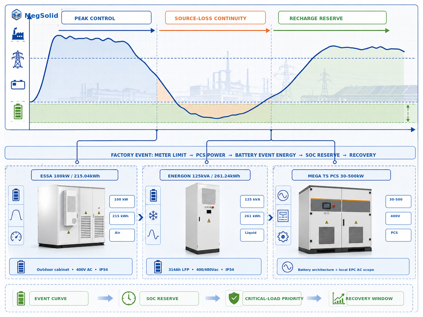
Battery energy follows the event curve. Each interval records the BESS power, interval duration, source contribution and SOC change. The total of those intervals sets event energy. The approved safe-stop or continuity reserve remains held for the next required state.
| Event stage | BESS duty | Data used | Battery-energy result |
|---|---|---|---|
| Before the production ramp | Charge only inside spare source capacity | Source headroom and starting SOC | Required starting reserve |
| Peak-control interval | Supply the meter gap | Interval kW and time | Peak-control energy |
| Source-loss interval | Supply the selected branch | Branch kW/kVA, source contribution and duration | Continuity energy |
| Safe-stop interval | Supply controls and ordered loads | Sequence loads and time per step | Safe-stop energy |
| Recovery window | Restore SOC reserve | Charge kW and available hours | Approved recharge requirement |
Published product paths for the event calculation
| Product path | Published model data | Factory duty it addresses | Project boundary before release |
|---|---|---|---|
| ESSA0100B-0215 outdoor cabinet | 100kW AC, 215.04kWh, LFP, intelligent air cooling, 400V AC and IP54 | Outdoor factory duty where the recorded PCS gap and event curve fit the 100kW / 215.04kWh envelope | Site route, usable dispatch window, protection, civil design and certificate scope |
| Meg-Solid Energon 261 | 125kVA, 261.24kWh, 314Ah LFP, liquid cooling, 400/480Vac ±15% and IP54 | Factory duty built around a 125kVA apparent-power requirement and liquid-cooled cabinet format | Active kW at the approved power factor, event duration, location and acceptance criteria |
| MEGA TS PCS | 30–500kW rated power, 33–550kVA maximum apparent output and 400V AC | 150kW to 500kW engineered factory duty with battery energy defined by the event curve | Battery compatibility, AC equipment, controls and source interface |
| ESSC containerised BESS | 500kW / 1.0752MWh and 1MW / 2.1504MWh, LFP and intelligent temperature-controlled air cooling | Larger factory load and longer-duration event path | Site electrical architecture, container access, installation and delivery scope |
The Energon 125kVA rating describes apparent power. The measured operating power factor sets the active kW available during the production event. Its published 90% maximum system-efficiency value is a product specification. Project round-trip efficiency, usable dispatch energy and performance acceptance remain project calculations.
Email the proposed single-line diagram, transformer details, available meter data, gas-turbine source information, equipment list and site layout to [email protected]. MegSolid will return an ESSA, Energon, MEGA TS or containerised-BESS product direction, plus the kW/kVA and kWh calculation structure for your local EPC.
Turn the Four EMS States Into a Commissioning Table
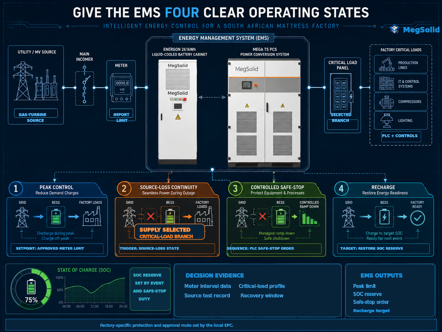
The EMS is the operating interface between the meter target, source status, battery reserve and critical-load branch. Each state needs a trigger, power rule, SOC rule, owner and measured exit condition. This turns the BESS from a cabinet selection into a repeatable factory operating process.
| EMS state | Trigger and action | SOC priority | Factory/EPC responsibility | Acceptance evidence |
|---|---|---|---|---|
| Peak control | Meter import reaches the approved threshold; PCS supplies the import gap | Preserve continuity reserve | Factory sets meter limit; EPC verifies meter/control wiring | Interval meter record stays at or below the approved target |
| Source-loss continuity | Source signal enters the defined loss state; PCS supplies selected critical branch | Hold continuity reserve through the approved event | Factory approves load list; EPC validates source signal and feeder route | Selected branch remains energised through the stated event |
| Controlled safe-stop | Production owner or protection logic calls the sequence; EMS supplies controls and ordered loads | Use safe-stop energy allocation | Factory supplies PLC sequence; EPC validates control interfaces | PLC record confirms ordered completion |
| Recharge | Event ends and verified headroom is available; BESS charges at approved limit | Restore operating reserve | Source owner confirms capacity; EPC validates charging interface | SOC reaches the agreed level before the next event |
Commissioning handover pack
- Controlled single-line diagram showing source, BESS, PCS, factory meter, selected panel, protection boundary and equipment owner.
- EMS operating-state table with triggers, meter limits, PCS setpoints, SOC reserve, recharge rule and source-loss response.
- Meter, source and selected-load test records that demonstrate each approved event.
- FAT/SAT plan with witness roles, alarm responses, recovery process and signed acceptance criteria.
Build ROI From the Meter Event and Production Event
The financial model must show where the BESS creates value and who owns each input. Demand charges, production continuity and installed project cost belong in separate lines. The model then remains aligned with the engineering system that the factory will commission.
| ROI line | Value the factory measures | Evidence source | Scope and decision owner |
|---|---|---|---|
| Meter-cost exposure | Cost linked to the recurring import interval | Tariff, electricity invoice, meter data and approved meter limit | Factory finance team sets cost model; EMS dispatch follows approved target |
| Production continuity | Avoided loss from interruption, restart, scrap, labour or delayed orders | Production records and management-approved value category | Factory production and finance teams |
| Source operating exposure | Operating effect of gas-turbine source and BESS sequence | Source records, run hours and local operating cost | Source owner, factory and local EPC |
| Delivered project cost | Equipment, AC work, cable, civil work, installation, approvals and commissioning | MegSolid scope, EPC scope and project quotations | Procurement team compares equivalent scope boundaries |
ROI review format
- Base case: tariff documents, approved production event and defined installed-scope boundary.
- Measured case: 15-minute demand record, validated source contribution and commissioning event data.
- Sensitivity case: longer source loss, reduced source headroom, increased production ramp or shorter recovery window.
The South Africa BESS ROI engineering page supports the wider financial discussion. The factory decision uses its own tariff, source and production evidence.
Release the BESS Through Clear Engineering and Procurement Gates
Every gate has a deliverable, an owner and a decision. This prevents the factory from releasing equipment before the local installation scope and operating evidence are ready.
| Gate | MegSolid output | Factory and local EPC output | Decision released |
|---|---|---|---|
| Engineering basis | Preliminary product direction and input register | Operating result, transformer data, proposed single line, equipment schedule, source description, tariff and layout | Candidate ESSA, Energon, MEGA TS or container product route |
| Configuration release | Product documentation and control-interface review | 15-minute load record, source test result, critical-load sequence, power-factor data and protection review | PCS kW/kVA, battery event energy, SOC reserve and recharge rule |
| Procurement release | Agreed equipment scope and delivery documentation | Responsibility matrix, general arrangement, local approval route, EPC price and FAT/SAT plan | Equipment and local EPC work packages |
| Commissioning acceptance | Agreed product and test documentation | Meter test, source-transition test, safe-stop test, recharge result and signed records | Installed system acceptance against the approved factory event |
The EPC energy storage evaluation framework helps teams compare the electrical, control, civil and commissioning boundaries. The South Africa BESS regulations route stays with the local EPC, engineer of record and authority-facing team.
Email the production-ramp target, selected critical loads, safe-stop sequence and gas-turbine source details to [email protected]. MegSolid will map peak control, source-loss continuity, safe-stop and recharge into an EMS operating table for the submitted factory scope.
FAQ
What does a mattress factory need to define before selecting commercial battery storage?
Define the production event, factory-meter boundary, selected critical-load branch, source contribution, event duration, required SOC reserve and recovery window. These values set the PCS and battery-energy calculation.
How does a factory choose between a 100kW ESSA cabinet and a 125kVA Energon system?
Use ESSA0100B-0215 when the recorded power gap and event energy fit the 100kW / 215.04kWh outdoor-cabinet route. Use Meg-Solid Energon 261 when the electrical design is built around a 125kVA apparent-power requirement and 261.24kWh liquid-cooled cabinet route. The recorded power factor sets usable active kW for the 125kVA system.
How is PCS power calculated for factory peak control?
Subtract the approved meter limit from the recorded factory demand for every peak interval. The highest required discharge gap sets the PCS active-power review. Record kVA and power factor with each interval.
How is PCS power calculated for a source interruption?
Subtract the validated source contribution from the simultaneous critical-load demand. The result sets the BESS active-power duty. Motor, VFD and compressor data sets the kVA and protection review.
How is battery energy calculated for a source event?
Add BESS output across every interval of the approved event curve, then hold the SOC reserve required for the next production or safe-stop event. The recharge calculation tests whether source headroom restores that reserve in time.
Can one BESS control peaks and support critical loads?
Yes. The EMS table gives continuity or safe-stop duty priority, reserves the associated SOC and limits peak-control dispatch to the energy above that reserve.
Why must the factory record kW and kVA separately?
kW defines active output. kVA defines the apparent-power envelope needed for the PCS, transformer and protection design. Production motors and power factor make both values necessary.
What does the gas-turbine source test need to show?
It needs to show the source connection point, firm kW contribution, voltage and frequency behaviour, protection interface, loss sequence and recovery sequence. These results set the source contribution and recharge rule.
What should the EMS do after a peak-control event?
It should recharge within approved source headroom until the continuity or safe-stop reserve is restored before the next event. The recharge limit protects factory production demand.
Which work remains with the local EPC?
The local EPC owns switchgear, cable, grounding, protection, source integration, civil work, installation, permitting, authority-facing approvals and field commissioning. Local PV procurement and installation also remain in the local scope.
How should the factory calculate BESS ROI?
Calculate meter-cost exposure, production-continuity exposure, source operating cost and delivered project cost as separate lines. Attach the tariff, meter record, production record and EPC scope to each line.
Does the 261.24kWh Energon system use solid-state batteries?
The published product data identifies 314Ah LFP cells. No hybrid-solid-state or semi-solid designation is published for the 261.24kWh configuration. Any cell-architecture claim uses the signed configuration documents.
Which product direction serves larger factory loads?
For a 150kW to 500kW measured PCS duty, use the MEGA TS PCS route with battery energy calculated from the event curve. For larger requirements, use the 500kW / 1.0752MWh or 1MW / 2.1504MWh ESSC containerised BESS routes.
What data sets commercial battery storage system size for a South African factory?
The factory event curve sets BESS size. Record factory kW, kVA, power factor, meter limit, selected critical loads, validated source contribution, event duration, SOC reserve and recovery window. These values set PCS power and battery energy separately.
Which MegSolid product route fits a 100kW factory BESS duty?
ESSA0100B-0215 is the published 100kW AC and 215.04kWh outdoor-cabinet route. It uses LFP cells, intelligent air cooling, 400V AC and IP54 protection. The factory event curve establishes the approved duty and energy reserve.
What should a factory send for a preliminary BESS system direction?
Send the proposed single-line diagram, transformer details, available 15-minute load record, tariff, gas-turbine source information, production event, critical-load list, safe-stop sequence and site layout. MegSolid maps these inputs to a BESS product route and EPC interface list.