
Buying a lithium battery for 5G base station backup on Ah alone can leave the next outage uncovered. MegSolid RL10E200-L offers 10.24 kWh with 200 A maximum continuous charging; RL10E200-X holds the same energy with a 100 A limit. Buy for the backup hours and the charging window that must restore them.
**Prioritize RL10E200-L in the comparison when the verified duty needs more than 100 A, up to 200 A, per pack.** The source must supply that current while serving the site. When insufficient stored energy is the problem, compare RL15E280-L and RL16E314-X.
These RL batteries use wall-mounted or household-storage formats, not prequalified 19-inch telecom rack modules. Start telecom battery procurement with an approved mounting and electrical design. The model comparison below supports that evaluation; it is not authorization for a drop-in replacement.
How Much Backup Energy Does the 5G Upgrade Actually Need?
More radio load on an unchanged battery bank can shorten backup just when the site has more equipment to support. “5G-ready” on the quotation does not close that gap. Establish the energy required at the protected load before selecting a replacement.
Measure every protected circuit at the agreed DC delivery point and follow the combined demand through the day. One radio's rating leaves out the rest of a multi-tenant site. The bank has to cover the whole specified load, not the easiest part of it.
Four hours at 4 kW requires 16 kWh at the load
Use a defined buying requirement: **4 kW for four hours**.
**Required delivered energy = 4 kW × 4 h = 16 kWh.**
One RL10E200-L or RL10E200-X holds 10.24 kWh nominal energy; RL15E280-L holds 14.336 kWh. Neither size reaches the 16 kWh load requirement before losses. RL16E314-X reaches 16.07 kWh, leaving just 0.07 kWh before reserve, delivery losses and ageing.
**“Almost the same kWh” is not a four-hour backup design.**
The energy screen below uses an 80% usable SOC window, a 95% battery-to-load delivery factor and an 80% retained-capacity criterion. These are sizing inputs, not MegSolid performance guarantees. Check temperature effects, power limits and any auxiliary demand outside the stated load separately.
| Same-model configuration | Combined nominal energy | Calculated load energy under those inputs | Result against 16 kWh |
|---|---|---|---|
| 2 × RL10E200-L | 20.48 kWh | 12.45 kWh | Insufficient |
| 2 × RL15E280-L | 28.672 kWh | 17.43 kWh | Passes this energy calculation |
| 2 × RL16E314-X | 32.14 kWh | 19.54 kWh | More calculated energy margin |
**Calculated load energy = nominal energy × 0.80 × 0.95 × 0.80.**
**Evaluate two RL15E280-L packs first within this two-pack comparison.** Two RL10E200-L packs miss the energy requirement; two RL16E314-X packs add calculated margin. This is an energy screen, not a complete-site approval or redundancy result. Mounting, electrical integration and actual operating conditions must also be checked.
The backup SOC reserve must be there when the grid fails. Aged capacity, earlier discharge and incomplete recharge all reduce it. The purchase order cannot supply energy that never made it back into the bank.
Which MegSolid RL Battery Fits the Current Limit and the Site?
All four models carry a 51.2 V nominal rating. Their capacity, current limits, temperature ranges and enclosures still lead to different purchases. More kWh addresses runtime; higher charging capability helps recovery only when spare source power is available.
| Model | Nominal capacity / energy | Maximum continuous charge / discharge current | Charge-temperature range | IP rating |
|---|---|---|---|---|
| RL10E200-L | 200 Ah / 10.24 kWh | 200 A / 200 A | 0–55°C | IP21 |
| RL10E200-X | 200 Ah / 10.24 kWh | 100 A / 100 A | 0–60°C | IP31 |
| RL15E280-L | 280 Ah / 14.336 kWh | 200 A / 200 A | 0–55°C | IP21 |
| RL16E314-X | 314 Ah / 16.07 kWh | 200 A / 200 A | 0–55°C | IP31 |
Specification basis: RL10E200-L, RL10E200-X, RL15E280-L and RL16E314-X data sheets, V1.0, page 2. Installation and monitoring descriptions are on page 1.
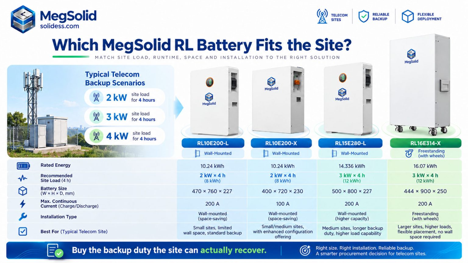
**RL10E200-L has the higher charging-current allowance: 200 A against RL10E200-X's 100 A.** Both store the same nominal energy. Check that the required per-pack current stays within the chosen limit at the operating conditions. If the source allocates only 80 A per pack, neither model can charge beyond that allocation.
Compare RL15E280-L and RL16E314-X when more nominal energy is needed per unit. Both retain a 200 A maximum continuous current limit. Evaluate the complete bank and its installation cost, not capacity per box alone.
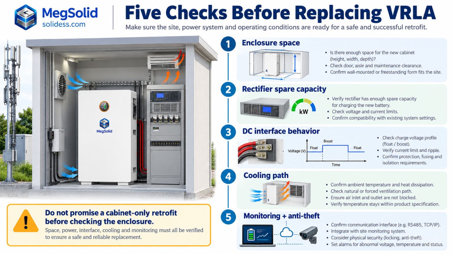
Check the battery enclosure before promising a cabinet-only retrofit
RL10E200-L measures **470 × 760 × 227 mm, W × H × D**, and weighs **96 kg**. RL10E200-X measures **400 × 230 × 720 mm, L × W × H**, and weighs approximately **93 kg**. Those are enclosure dimensions, not a 19-inch rack specification.
RL15E280-L weighs 128 kg. RL16E314-X weighs approximately 120 kg and stands 1,011.5 mm high with its wheels. The installation drawing needs to account for handling, restraint, mounting, cable access and service clearance before reusing site infrastructure is counted as a saving.
The L-series permits up to 20 parallel units; RL16E314-X lists up to 15. Use approved same-model arrangements, with the required current sharing and protection. Those limits do not authorize mixed banks or make these enclosures rack-compatible.
**Check the fit before placing the order. Otherwise, the retrofit can bring new site work instead of avoiding it.**
How Do Heat and Short Grid Windows Change the LFP-versus-VRLA Decision?
Replacing batteries without fixing the reason they lose reserve can leave the maintenance bill intact. Establish whether heat exposure, incomplete recharge or both are responsible. Compare the RL configuration against those conditions and the actual VRLA replacement history.
Check charging current at the actual enclosure temperature
RL10E200-L, RL15E280-L and RL16E314-X list charging operation from 0°C to 55°C. RL10E200-X lists 0°C to 60°C. All four list discharge operation from −20°C to 60°C.
Check permitted charging current at the actual enclosure temperature. The stated temperature ceiling is not proof of full-current operation at that temperature, and it does not establish calendar life. Radios and controllers retain their own cooling requirements.
Base the replacement plan on the existing VRLA bank's temperature and service records and the proposed LFP duty and warranty. Neither a fixed twelve-month VRLA life nor five replacement-free lithium years should be assumed for the site.
Include thermal management in the installed price. Harsh-site battery selection must keep the required runtime and recharge performance available in the enclosure, not just put a wider temperature range on the quotation.
Charging current only helps when the source has spare capacity
Dividing maximum charge current by capacity gives **1C for RL10E200-L**, **0.5C for RL10E200-X**, approximately **0.714C for RL15E280-L**, and approximately **0.637C for RL16E314-X**.
These ratios describe current capability. Starting SOC, temperature, spare source capacity and charging taper determine the time needed to recover the reserve.
Recovering the 16 kWh used by the specified site in two hours requires at least **8 kW of average charging power**, before losses. The protected load continues to use 4 kW, bringing the ideal lower bound to **12 kW at the DC distribution boundary**. Allow separately for conversion losses, auxiliaries and charging taper.
| Rectifier output available at the DC bus | Protected site load | Ideal spare charging power | Ideal time to replace 16 kWh |
|---|---|---|---|
| 6 kW | 4 kW | 2 kW | 8 hours |
| 8 kW | 4 kW | 4 kW | 4 hours |
| 12 kW | 4 kW | 8 kW | 2 hours |
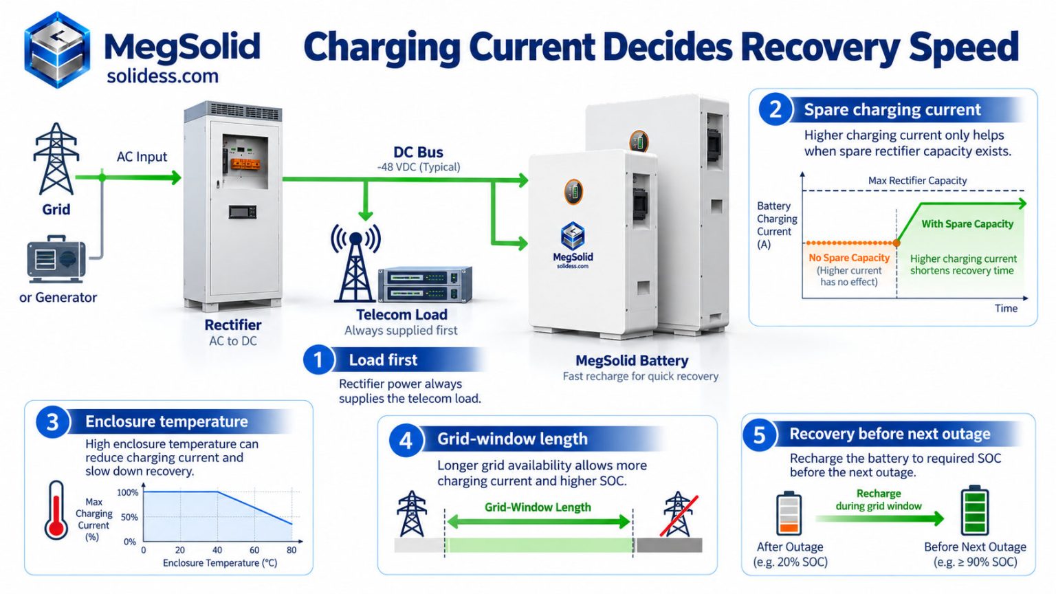
**Faster battery charging cannot recover energy that the rectifier never supplies.**
Divide the bank's charging requirement across the proposed packs. RL10E200-X can remain a current-rated candidate when each pack stays within 100 A. Prioritize RL10E200-L where the verified requirement is higher, up to 200 A. This current check does not replace the energy calculation.
Get a comparison of RL capacity and charging-current options against the proposed backup hours, recharge window and installation constraints.
Which Cooling, Monitoring and Security Costs Can Actually Fall?
Cooling, maintenance visits and site security can continue to cost money after the batteries change. Require each proposed improvement to address one of those expenses. The word “smart” does not turn a battery quotation into an operating saving.
Separate battery cooling from the rest of the shelter
Any cooling redesign must keep batteries, radios, transmission equipment and controllers within their operating limits. Use thermal assessment and metered energy to establish the reduction; do not work backwards from the saving needed to approve the project.
Put only the validated cooling reduction in the savings column. The remaining shelter cooling is still an operating cost. Charging the entire air-conditioning bill against VRLA but none against lithium would compare two different site services.
Use monitoring to identify the fault before a technician travels
RL10E200-X and RL16E314-X support PC-based BMS monitoring with real-time and historical data. Their described cloud/App route relies on communication through an inverter. The proposed telecom installation needs that data path verified before remote diagnostics can be counted as an operating benefit.
The L-series BLE functions cover status checks, BMS configuration and firmware servicing, with Bluetooth listed as optional. That is useful for local maintenance. It does not by itself give an operations centre unattended access to every tower battery.
The separate ES-01/ES-02 EMS family lists third-party platform access, logs, fault reports and multi-energy dispatch in its V1.1 sheet. Hardware includes five RS485 ports, two CAN ports, two Ethernet ports and one 4G interface. Provide the specified 9–36 V DC supply; the controller must not be connected directly to a 51.2 V battery.
Follow a fault through the BMS and EMS communication architecture: battery report, controller interpretation and receipt at the network operations centre. Verify the messages and commands at each step. Matching ports cannot show whether the operator receives a useful alarm.
Treat anti-theft as a separate, tested function
Physical restraint, access control, tamper alarms and asset identification should match the site's security risk. GPS tracking, geofencing, SNMP integration and remote locking are separate requirements—not established standard RL features. Any implementation needs identified hardware, software and acceptance evidence.
Remote locking also needs authorized access and a tested recovery procedure. An accidental lockout that removes backup supply creates an availability risk. Test the failure behaviour as carefully as the intended security action.
**Monitoring earns its place when it helps diagnose the fault before the technician travels. The dashboard alone cannot do that.**
How Should Solar, Diesel and Batteries Share a Weak-Grid Telecom Site?
Reducing generator hours while leaving the battery undercharged can make the next outage harder to cover. The solar–diesel schedule must supply the day's load and restore the reserve. Engine runtime is only one part of that result.
The specified 4 kW protected load consumes **96 kWh per day**, excluding other loads. Two RL15E280-L packs hold 28.672 kWh nominal energy. Storage helps bridge the supply gaps; solar, grid or diesel still has to supply the day's energy and the associated losses.
**Battery capacity can move energy through time. It cannot replace the daily energy source.**
Show the supply path on the approved drawing: AC source, rectifier, solar conversion equipment, battery connection and protected DC loads. The RL packs provide storage, not AC generation or solar regulation. Telecom rectifier compatibility remains part of that design.
Dispatch around the recovery requirement
When supply returns, serve the operating load and use verified spare capacity to recharge. If solar leaves an energy shortfall, generator scheduling must close it within the selected engine's permitted operating range.
Set generator starts, output and stops from measured demand, reserve needs and the selected engine's permitted loading and fuel curve. Do not confuse a loading percentage with efficiency or impose “85% efficiency” as a universal target.
Use diesel–BESS control coordination to define source operation. Then validate the telecom rectifier and DC distribution separately; an AC microgrid control concept does not establish their compatibility with an RL battery.
The two-pack RL10E200-L arrangement has a higher aggregate charge-current ceiling than the corresponding RL10E200-X arrangement. Source power, current sharing, wiring, protection and controls decide how much of it the installation can use.
The energy-management priorities should protect the next outage reserve. Stopping the engine before that reserve is restored may save fuel in one interval while leaving the site exposed in the next.
What Belongs in a Five-Year Telecom Battery TCO?
The lowest quotation can buy the most expensive operating problem. Compare complete installed alternatives over five years against the same protected load, backup duration, recharge window and availability requirement. An offer that supplies less service has not won the comparison.
Reject configurations that fail the duty before comparing TCO. That includes an undersized lithium bank and a VRLA bank unable to recover between the site's outages. Chemistry does not excuse either shortfall.
| Five-year cost item | What the comparison must include |
|---|---|
| Initial installed cost | Batteries, approved mounting, protection, cabling, controller changes, freight and installation |
| Replacement and capacity restoration | Timing, labour, logistics and replacement scope supported by the actual duty and warranty |
| Energy | Charging losses, generator fuel and the cooling that the installed configuration still requires |
| Site maintenance | Planned servicing, diagnostics, technician travel and spare-stock arrangements |
| Monitoring and security | Controllers, communications, licences, installation and demonstrated security measures |
| End-of-period value | Consistent treatment of residual value, removal and disposal across both options |
**Five-year TCO = installed cost + operating costs + replacement costs + end-of-period costs − residual value.**
Use the same currency, price basis, tax treatment and discounting method for both options. Assess unmeasured service-loss exposure separately from cash savings; do not turn a risk estimate into revenue already earned.
Put the higher charging allowance where it earns its keep
At 80 A allocated per pack, the 200 A RL10E200-L rating offers no charging-power advantage over the 100 A RL10E200-X rating. The case for the L version appears when verified demand exceeds 100 A, remains within 200 A and the source can supply it.
Compare the installed RL15E280-L or RL16E314-X bank with the smaller-pack configuration meeting the same runtime. The change in unit count also changes handling, protection and mounting work; price the whole arrangement.
RL10E200-X's five-year warranty and 6,000-cycle statements need to be read against the agreed battery warranty conditions for the application, temperature, cycling and retained capacity. They do not establish replacement-free telecom service or the warranty of another RL model.
Price the cooling reduction the site can measure
If the validated cooling redesign removes 0.2 kW for 12 hours per day, the calculated annual reduction is **876 kWh per site**. Apply the site's avoided electricity or fuel cost to that reduction, then include the redesign cost in the comparison. This is a conditional calculation, not measured site savings.
An 18–24-month payback cannot be read from a lithium data sheet. It has to emerge from the installed premium and verified operating benefit while the same backup obligation is met.
Which Rectifier and DC-Interface Checks Decide Whether the Retrofit Works?
RL10E200-L and RL15E280-L specify a **57.6 V charging cutoff**; RL10E200-X and RL16E314-X specify **58.4 V**. All four specify a **44.8 V discharge cutoff**. These pack-terminal values are not instructions for setting the radio supply bus.
ETSI EN 300 132-2 V2.7.1 defines a nominal −48 V ICT input interface and a normal service range from −40.5 V to −57.0 V at that interface. Battery-terminal voltage, load-terminal voltage and earthing must be treated separately. The pack's “51.2 V” label does not establish compliance.
Determine whether the battery system and load have an approved common voltage window or need a suitable conversion interface. Test delivered energy at the final charging settings. Lowering the charging limit to suit an interface can also change the energy recovered.
Verify commands and failure behaviour, not just ports
Validate the selected rectifier model, firmware, current allocation and battery control. Check messages, alarms, enforced limits and loss-of-communications behaviour. RS485 or CAN describes the interface; the tested exchange of data establishes whether the controls work together.
Witness source loss, recharge under the running load, loss of one battery branch and the next discharge. The sequence must demonstrate recovery as well as the first backup event. Parallel capacity alone does not establish branch-failure tolerance.
IEC 62619:2022 addresses industrial lithium-cell and battery safety requirements and tests, including telecom applications. Obtain evidence for the offered model and operator acceptance. This standards reference is not certification of the RL products.
Use functional acceptance testing on the ordered arrangement. **Prove the retrofit at the load before repeating its connection design across a network.** One successful bench charge alone does not establish that result.
Purchase the Backup Duty the Site Can Actually Recover
MegSolid's RL range separates two decisions: **10.24 kWh with either 100 A or 200 A maximum continuous charging**, or 14.336 kWh and 16.07 kWh options with 200 A limits. Match the selection to the site's energy shortfall and actual charging capacity.
Use RL10E200-L as the higher-current candidate when the approved requirement is above 100 A and within 200 A per pack. Compare RL15E280-L and RL16E314-X when delivered energy is the constraint. Keep a purpose-built rack solution on the shortlist wherever the site cannot accept an approved RL mounting arrangement.
The replacement must carry the load, recover before the next outage and remain serviceable through the contract. Leaving any of those duties unresolved can put a new battery on the same old operating problem.
**Buy the operating result. Do not pay for a battery label that the installed power system cannot use.**
Contact MegSolid to compare the RL candidates and identify the mounting, voltage, recharge and monitoring requirements that must be resolved before a site pilot.
FAQ
Is a 51.2 V lithium battery automatically suitable for a −48 V telecom bus?
No. Validate the permitted load-interface voltage, return/earthing arrangement, protection and charger control together. Nominal voltage alone does not approve the connection.
Which 200 Ah RL model offers the higher charging-current allowance?
RL10E200-L provides the higher limit: 200 A maximum continuous charging, compared with 100 A for RL10E200-X. Both store 10.24 kWh nominal energy.
Does the RL10E200-L rating guarantee a one-hour recharge?
Its 200 A/200 Ah ratio equals 1C. Time to restore the required energy depends on starting SOC, temperature, permitted current, charging taper and spare source capacity; one-hour recovery is not established by the ratio.
Can one 16.07 kWh battery supply a 4 kW site for four hours?
That duty needs 16 kWh at the load, leaving just 0.07 kWh of nominal margin. It is insufficient as a design basis once reserve, delivery losses and ageing allowances are included.
Are the RL products standard 19-inch telecom rack modules?
These RL models use wall-mounted or household-storage formats, not standard telecom rack modules. Check the installation design against their actual dimensions; rack-only sites need the appropriate product format.
Can lithium and existing lead-acid batteries be connected directly in parallel?
Similar nominal voltage is not permission to parallel different chemistries. Use a specifically engineered and approved arrangement addressing charging limits, current sharing, isolation and faults.
Will changing to LFP remove the shelter's cooling requirement?
Thermal assessment must establish what the installed redesign can remove. Keep batteries and all other equipment within their limits, and count only the validated cooling reduction.
Does RS485 or CAN prove compatibility with a particular rectifier?
No. Check the selected firmware's handling of battery messages, permissible currents, alarms and communication failures. The port label is not proof of the complete control exchange.
Do the RL packs include GPS and remote anti-theft locking?
Do not assume these are standard RL functions. Tracking or immobilization needs separately specified hardware, communications, authorization and a tested recovery procedure.
Is an 18–24-month payback assured when replacing VRLA?
No. Compare installed prices, energy, servicing, replacements and monitoring for two configurations meeting the same duty. Those costs and benefits determine the result.
How should a Nigerian or Kenyan weak-grid site set its recharge requirement?
Use the recorded outages and available charging periods at the actual site. The rectifier must carry the running load first; only its remaining capacity can recharge the bank.
What should Indonesian or Philippine outdoor sites check beyond temperature?
Check rain, moisture, dust, mounting and maintenance access at the installed location. IP21 or IP31 RL packs require an appropriate installation arrangement; they are not complete outdoor tower cabinets.
Can a TowerCo use one battery design across several countries?
Shared specifications can standardize tested equipment and records. Approve each site class for its electrical conditions, environment, installation and applicable local requirements.