
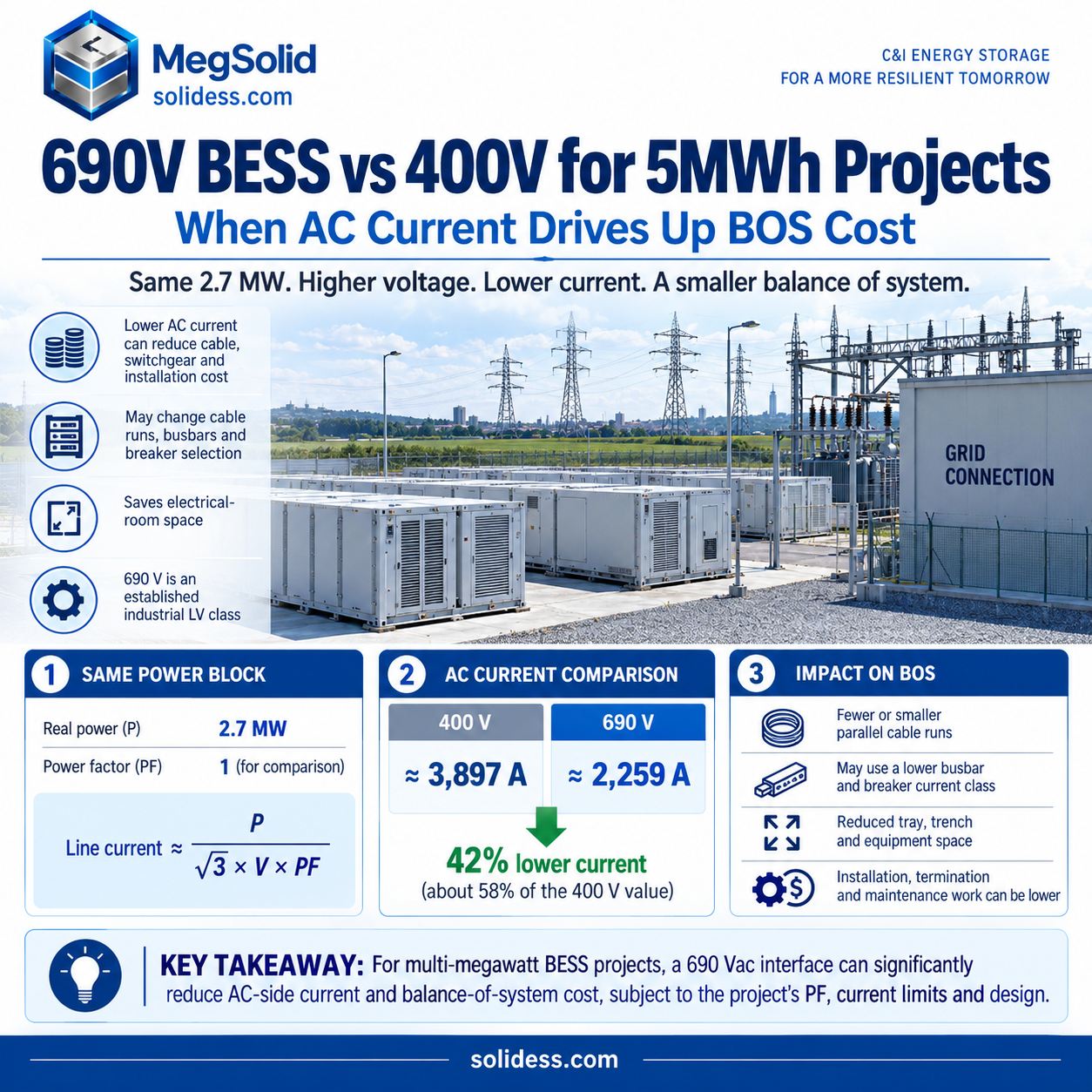
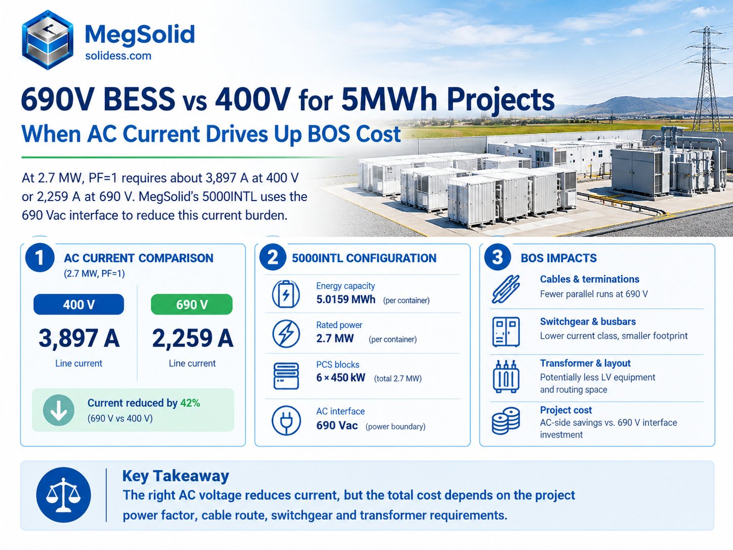
EPCs comparing 5 MWh battery quotations can face a larger installation bill once they size the AC cables and switchgear, particularly at 2.7 MW. At PF=1, that power requires about 3,897 A at 400 V or 2,259 A at 690 V. MegSolid’s 5000INTL uses the 690 Vac interface to reduce this current burden.
That current drives cable runs, terminations, busbars, breakers and switchgear sections, all of which consume electrical-room space.
MegSolid’s 5000INTL containerized BESS combines 2.7 MW / 5.0159 MWh, six 450 kW PCS blocks and a 690 Vac power boundary. Sizing the AC connection also requires the project power factor and current limits; PF=1 is only the basis of this comparison.
The purchase decision comes down to whether AC-side savings outweigh the transformer and interface work required for 690 V equipment.
2.7 MW Changes the AC-Voltage Decision
Size the AC path from real power, voltage and power factor:
Line current ≈ real power ÷ (√3 × line voltage × power factor)
Using 2.7 MW and PF=1 only to isolate the voltage effect:
| Power block | AC voltage | Approx. line current |
|---|---|---|
| 2.7 MW | 400 V | 3,897 A |
| 2.7 MW | 690 V | 2,259 A |
Changing only the voltage reduces the theoretical current to about 58% of the 400 V value, roughly 42% lower.
Theoretical current falls by 42%, but cable and switchgear savings still have to be priced from the actual design. The current assessment needs the project power factor, overload/current limits, harmonics and design margin. Cable ampacity also depends on ambient temperature, conductor grouping, installation method and permissible temperature rise.
Lower PCS-side current can change the LV equipment class or the number of parallel cable runs. At several megawatts, busbar and breaker selection, together with cable-routing space, can influence which BESS fits the project.
Nearly 3,900 A Moves Cost Into the Balance of System
At several thousand amperes, the route between PCS, transformer and switchgear can account for substantial equipment and installation work. It belongs in the balance-of-system (BOS) quotation alongside the battery installation.
Illustrative 35 m transformer-route screen
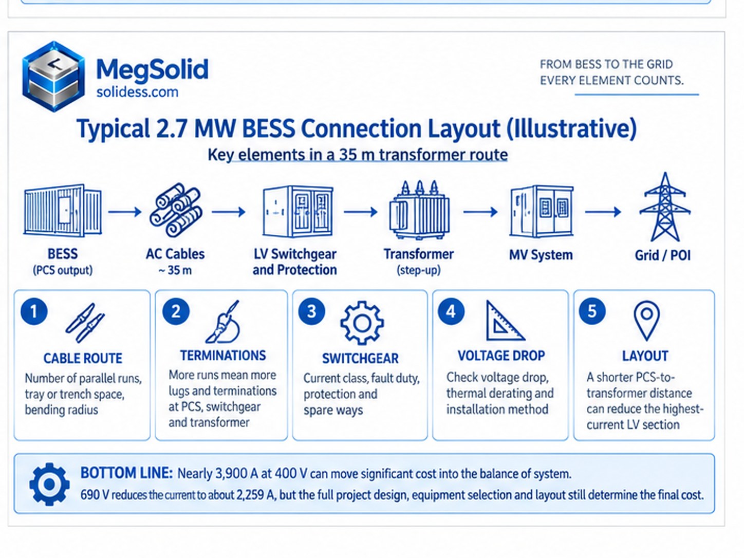
In this illustrative 2.7 MW layout, the transformer sits 35 m from the BESS. Cable size and parallel-conductor count have not yet been selected; the first comparison is between the two voltage options over that route.
At PF=1, the EPC would be screening roughly 3.9 kA over that LV route at 400 V versus about 2.26 kA at 690 V. Before accepting either architecture, the design team would compare:
- the number of parallel conductors required by the selected cable system;
- tray, trench and bending-space requirements;
- termination count at the PCS, switchgear and transformer;
- breaker and busbar current class;
- voltage drop and thermal derating;
- whether moving the transformer closer to the PCS can shorten the highest-current LV section.
Cable route, switchgear and transformer position give the estimator the basis for pricing both layouts. The cheaper battery package may require more installation work along the 35 m route.
Parallel cable runs can multiply
Meeting the required ampacity may take several parallel conductors per phase. Each run adds cable and lugs, occupies tray or trench space and has to fit the available bending radius. The design must account for current sharing and grouping derating across those paths. Installation, inspection and maintenance also increase with the number of runs.
Route length and installation method determine the cost of the additional conductors and terminations. Compare the proposed cross-site route with a short PCS-to-transformer connection.
Busbars move into a higher current class
Busbars must carry the continuous current within the permissible temperature rise, with enough ventilation around joints and connection points. Their short-circuit withstand must match the project fault study. Physical segregation, expansion and maintenance access can increase the required distribution footprint without changing the battery enclosure.
Switchgear becomes part of the product decision
Check the existing factory switchboard for the current, fault duty and protection required by the multi-megawatt source. Apply the checks for a 400 V BESS connection to an existing switchboard: bus rating, breaker capacity, spare ways, protection and cable interfaces matter alongside voltage.
ABB’s MNS industrial low-voltage switchgear is specified for assemblies up to 690 V and up to 7,300 A, showing that 690 V is an established industrial LV equipment class used beyond BESS applications. ABB MNS technical information provides assembly ratings; match the selected configuration to the project fault level, breaker arrangement and installation standard.
Electrical-room space can grow around the current
Switchgear line-ups need room for cable entry and terminations, with trenches or bus ducts taking more space. Heat rejection also affects the layout. Accommodating the higher-current equipment can cost more than the saving on the battery package.
5000INTL Uses 690 Vac at the Multi-Megawatt Power Block
MegSolid divides the 5000INTL’s 2.7 MW rated AC power across six 450 kW PCS blocks at 690 Vac. Its published ratings provide the starting point for the electrical design:
| Parameter | MegSolid 5000INTL |
|---|---|
| Rated energy | 5.0159 MWh |
| Rated AC power | 2.7 MW |
| PCS structure | 450 kW × 6 |
| Rated AC voltage | 690 Vac |
| Nominal DC voltage | 1331.2 Vdc |
| DC operating range | 1123.2–1497.6 Vdc |
| Cooling | Smart liquid cooling |
| Enclosure | IP55 |
| Dimensions | 6058 × 2438 × 2896 mm |
| Operating temperature | −30 to 55°C |
Feeder and protection design must follow the six-block PCS arrangement. The aggregate current calculation alone does not define the connections for individual PCS outputs.
The required discharge duration needs to fit the 5.0159 MWh energy rating, while the power requirement needs to fit 2.7 MW. The BESS power-to-energy ratio must match the site duty.
Smart liquid cooling and IP55 address thermal management and enclosure protection. Review those functions in the 5000INTL 5 MWh BESS architecture alongside the AC-interface assessment.
Send the target MW/MWh, site voltage and proposed point of interconnection. MegSolid can return a preliminary comparison of the 400 V and 690 V current classes and show where the transformer boundary would need to sit.
Match the 690 V Output to the Site Connection
The 5000INTL’s 690 Vac power block needs an engineered interface to the site voltage, whether 400 V, 10 kV, 11 kV, 20 kV, 33 kV or another specified value. The electrical path may include a transformer, LV or MV switchgear, protection, earthing, metering, cables or bus duct and utility interconnection equipment.
Transformer Position Sets the High-Current LV Route
Transformer position determines the length of the high-current LV route. An MV-connected project can shorten it by placing the transformer close to the 690 V PCS boundary. Factories operating at 400 V need to weigh the added 690 V-to-400 V interface cost against the AC-side savings.
Industry equipment follows the same pattern. Sinexcel publishes a 2.5 MVA medium-voltage storage station with a 690 V LV transformer side and 12/24/36 kV MV options, illustrating a commercial 690 V-to-MV storage architecture. Sinexcel 2.5 MW MV station specification is an industry reference, not a MegSolid project design.
Define the Site Connection Boundary Before Comparing Voltages
The commercial BESS interconnection boundary must be established before comparing the voltage options. The transformer ratio must match both the 690 V BESS boundary and the project-side connection voltage.
400 V Can Still Win at Lower Power
MegSolid offers 400 V containerized systems for lower-power duties:
- ESSC0500B-1075 , 500 kW / 1.0752 MWh, 400 V, 722 A
- ESSC1000B-2150 , 1 MW / 2.1504 MWh, 400 V, 1,445 A
The ESSC containerized BESS range provides these alternatives to the 690 V 5000INTL.
The 500 kW option puts the connection in the roughly 700 A class; 1 MW reaches the 1.4 kA class. Existing switchboard, cable and transformer capacity determine whether those currents fit. With suitable switchgear and a short LV route, either duty may remain at 400 V without another voltage interface.
At 2.7 MW, the current approaches 3.9 kA at PF=1. Parallel cables, busbar size and breaker class need a fresh comparison at the proposed transformer position. The complete BOS design can still show 400 V as the better route.
Compare Current Across the Required Power Range
Use the following current calculations to assess the required power range at each voltage:
| Real power | 400 V, PF=1 | 690 V, PF=1 |
|---|---|---|
| 500 kW | ≈722 A | ≈418 A |
| 1 MW | ≈1,443 A | ≈837 A |
| 2 MW | ≈2,887 A | ≈1,673 A |
| 2.7 MW | ≈3,897 A | ≈2,259 A |
Apply the project’s electrical and installation conditions before using these comparison values to select cables.
The economic crossover depends on switchgear availability, cable routing, allowable parallel conductors and busbar architecture. Transformer position, short-circuit level and redundancy topology also affect the cost at the specified connection voltage. Both options must meet local installation standards.
Sites with suitable equipment and short routes may retain 400 V above 1 MW. Long routes or limited space in the LV room can make cable and switchgear constraints significant at a lower power.
The operating duty and connection boundary established in the C&I BESS system design determine whether a higher AC voltage offers a purchasing advantage.
Compare the BOS Quote With the BESS Quote
Every battery offer needs a defined AC installation scope. The 400 V price must cover parallel cables, higher-current switchgear, busbars and terminations, with the cable routes and LV-room space accounted for. The 690 V quotation needs its own conductor arrangement and switchgear class, plus transformer placement, installation labour and the electrical-room footprint.
Compare both proposals using the same scope:
BESS package + cable + busbar + switchgear + transformer + installation + electrical-room impact
Complete that CAPEX comparison before calculating BESS LCOS so the lifetime-cost model includes the required balance-of-system equipment.
Connect the 690 V Power Block to MV at the Correct Boundary
Large industrial and grid-facing projects typically place a transformer between the PCS power block and the site or utility MV system.
The conceptual path is:
5000INTL 690 V AC → project transformer → MV switchgear → plant or grid connection
The transformer ratio must connect the 690 V LV side to the specified site voltage. Connections at 10 kV, 11 kV and 33 kV require different ratios.
Protection also follows the complete topology:
- PCS-side protection;
- LV fault duty;
- transformer protection;
- MV breaker;
- earthing;
- metering;
- utility protection;
- operating and anti-islanding logic where applicable.
The Sinexcel reference above uses copper bar or cable between LV and MV sections. Specify that connection, the transformer and protection for the MegSolid project’s topology.
The cabinet versus containerized ESS architecture affects where these interfaces sit. Several cabinet-scale 400 V blocks and one 5 MWh / 690 V container do not create the same cable or transformer topology.
Select 5000INTL From the Complete AC-Side Comparison
The MegSolid options below sit in different power and energy classes. Their installation scope determines which AC voltage makes sense for the site.
| Project condition | MegSolid route | Procurement reason |
|---|---|---|
| ~500 kW / ~1 MWh and 400 V infrastructure can accept the duty | ESSC0500B-1075 | 500 kW / 1.0752 MWh already fits the lower-power container class |
| ~1 MW / ~2 MWh with acceptable 400 V current and short LV connection | ESSC1000B-2150 | 1 MW / 2.1504 MWh keeps the project in a 400 V architecture |
| Around 5 MWh with conversion power reaching 2.7 MW | 5000INTL | 690 V lowers the PCS-side current compared with the same power at 400 V |
| Site is 400 V but multi-MW cable and switchgear become excessive | 5000INTL + engineered transformer/interface | Move the voltage-conversion boundary instead of forcing the entire 2.7 MW block through 400 V |
| Transformer and site changes erase the 690 V BOS benefit | Recompare the complete 400 V and 690 V installed cost | Voltage alone must not dictate procurement |
Select 5000INTL where its 2.7 MW / 690 V interface reduces enough cable, switchgear and layout cost to justify the transformer and site-connection work. The quotation should state the selected current class and transformer location so the price matches the intended AC architecture.
Send the site voltage, transformer arrangement and proposed BESS connection point. MegSolid can assess the initial fit of 5000INTL and identify the AC-side interfaces that still need project engineering.
FAQ
Can a 690 V BESS connect directly to a 400 V switchboard?
No. The 690 V BESS output and 400 V switchboard operate at different voltages. The project needs an engineered transformer or other approved voltage interface, together with switchgear, protection and earthing appropriate to the final topology.
Why is the current so high for a 2.7 MW BESS at 400 V?
Three-phase current rises as voltage falls for the same real power and power factor. At PF=1, 2.7 MW is approximately 3,897 A at 400 V and 2,259 A at 690 V. Apply project conditions before selecting final design currents.
Does 690 V make a BESS 42% cheaper?
No. The approximately 42% figure refers only to the reduction in theoretical line current when comparing 690 V with 400 V at the same power and PF. Cable, switchgear, transformer, protection and installation costs have to be priced separately.
When is a 400 V BESS still the better choice?
400 V can remain the better architecture when the power block is smaller, the LV route is short, suitable switchgear already exists and adding another transformer or voltage layer produces no useful BOS saving.
Does the MegSolid 5000INTL include an MV transformer?
The current published 5000INTL product data defines a 690 Vac BESS power block but does not list an integrated project MV transformer. The transformer and grid-side interface require project engineering unless the controlled quotation states otherwise.
What is the difference between 5.0159 MWh and 2.7 MW on the 5000INTL?
The 5.0159 MWh value is rated energy. The 2.7 MW value is rated AC power. More MWh extends the available energy duration; it does not increase PCS power above 2.7 MW.
Can 690 V reduce the number of parallel AC cables?
It can reduce the current that must be carried for the same power, which may change conductor quantity or parallel-run requirements. The actual cable arrangement still depends on ampacity, route length, installation method, temperature, grouping, voltage drop and project standards.
Is 690 V switchgear difficult to source?
690 V is an established industrial low-voltage class. ABB, for example, publishes MNS switchgear assemblies up to 690 V and several-thousand-ampere busbar ratings. Actual availability, fault rating, form of separation and breaker configuration remain project-specific.
Should the transformer be placed close to the BESS?
Placing the transformer nearby can shorten the highest-current LV run. Site layout, transformer type, fire separation, cable route, maintenance access, losses and MV architecture all affect the optimum position.
Can a 5 MWh project use several 400 V containers instead of one 690 V 5000INTL?
Yes, if the required power, energy, redundancy, current, switchgear and cable architecture support that route. Compare the complete installed BOS for the required container quantities.
Can a 690 V BESS be used on European industrial sites?
Yes, subject to the project standards and connection design. 690 V is a recognized industrial LV equipment class, but the BESS still has to be integrated with the site transformer, switchgear, protection and utility requirements.
Can the 5000INTL connect to an 11 kV, 20 kV or 33 kV site?
Potentially, through a project-specific transformer and MV interface. The required transformer ratio and switchgear depend on both the 690 V BESS boundary and the actual site voltage; the 5000INTL rating alone does not define that MV equipment.
Is a 690 V-to-MV BESS architecture already used in the storage industry?
Yes. Published industry equipment includes multi-megawatt storage stations with a 690 V transformer LV side and MV outputs. That confirms the architecture is established, although every MegSolid project still needs its own transformer and protection design.