
A 400V BESS connection should begin with the existing switchboard, not with a battery-cabinet quotation. The buyer must prove that the board can carry bidirectional current, interrupt the available fault current, maintain protection selectivity and support the required operating mode. This guide gives facility owners, consultants and EPC teams a practical route from site data to a decision-ready single-line diagram (SLD) and RFQ.
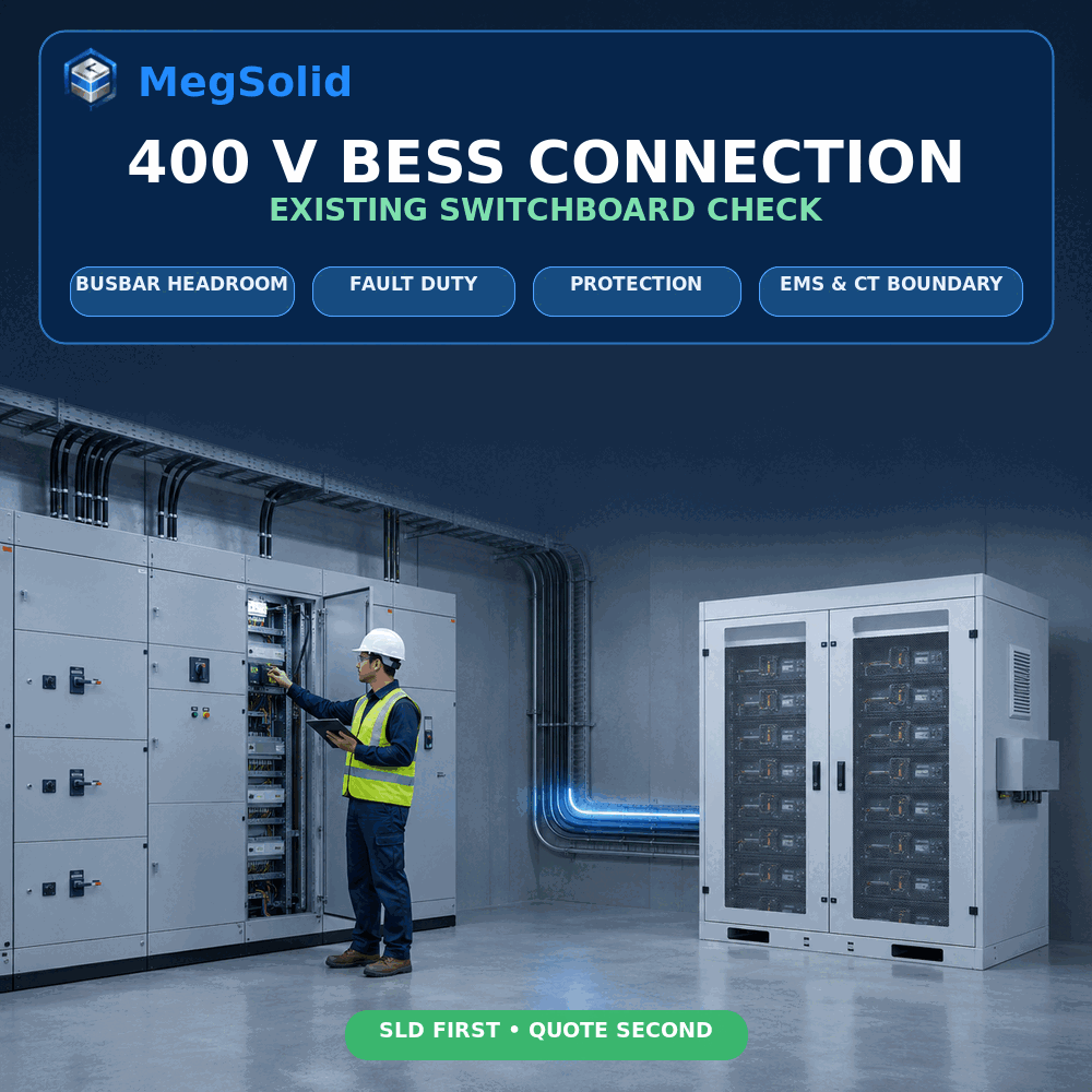
- ⚡ Current path: Confirm busbar rating, spare-way rating, cable route and thermal headroom in both charge and discharge directions.
- 🛡️ Fault path: Verify prospective fault current, breaker interrupting duty and the additional source contribution created by the PCS.
- 🔄 Operating mode: Separate grid-connected peak shaving from selected-load backup or whole-site islanding.
- 🌐 Control boundary: Place the revenue or control meter and CTs where the EMS can see every relevant source and load.
- 📐 Document boundary: Issue an approved SLD, protection concept, responsibility matrix and acceptance-test scope before purchase.
What Must Be Proven Before a 400V BESS Connection
A PCS rated at 400V may be a candidate for the site, but voltage alone does not prove compatibility. Confirm frequency, phase and neutral arrangement, allowable voltage range, isolation method, earthing system, protection functions and operating mode. MegSolid publishes several 400V interfaces, yet each family serves a different power, energy and integration boundary.
| MegSolid platform | Verified public AC interface | Use this only as an initial screen |
|---|---|---|
| ESSA outdoor cabinet | 400V; 320–460 V; 3W + N + PE; 30–100 kW and 55.296–215.04 kWh | Integrated isolation transformer; intelligent air cooling; project-specific solid-state cell option must be identified in the quotation and BOM |
| Meg-Solid Energon 261.24 kWh | 480 V / 400V ±15%; 125 kVA | 314 Ah LFP and liquid cooling; the public page does not identify this model as hybrid solid-state |
| MEGA TS PCS | 400V; 320–460 V; 3W + N + PE; 30–500 kW | Integrated isolation-transformer ratios vary by model; battery, switchgear and system scope remain project-specific |
| PMA modular PCS | 400V ±15%; 80, 105 or 125 kW; off-grid output 230/400V | Module-level PCS; transformer and complete-system integration are project-specific |
| ESSC containerized BESS | 400V; 320–460 V; 3W + N + PE; 500 or 1,000 kW | 1.0752 or 2.1504 MWh; LFP with intelligent temperature-controlled air cooling |
| 5000INTL | 690 V; 2.7 MW and 5.0159 MWh | Do not assume a direct 400V connection; an engineered voltage interface and site architecture are required |
Use the 100 kW / 215 kWh outdoor BESS selection guide to separate power from energy, and the 261 kWh liquid-cooled system RFQ guide when that cabinet class matches the duty. For a modular PCS boundary, compare the 105 kW energy-storage inverter buying guide. None of these pages replaces the switchboard study.
Define the Operating Mode Before Drawing the Feeder
The same BESS power rating can produce very different switchboard designs. A parallel feeder used for peak shaving normally remains grid connected. Backup service may require a separated essential-load bus, a transfer arrangement and explicit source-separation logic. Whole-site islanding adds load shedding, generator coordination, frequency and voltage control, and restoration sequencing.
| Required outcome | Connection implication | Question the RFQ must answer |
|---|---|---|
| Peak shaving or tariff shifting | Bidirectional feeder on the live 400V bus | What charge and discharge limit can the transformer, board and tariff boundary accept? |
| Zero export | PCC meter or CTs must close the EMS control loop | Which device measures net power, which device acts, and what is the fail-safe state? |
| Selected-load backup | Essential loads need a defined backup bus and transfer boundary | Which loads remain energized, for how long, and how are sources prevented from unsafe parallel operation? |
| Islanded microgrid | Grid-forming and load-management duties must be allocated | Who owns black start, generator synchronization, load shedding and return-to-grid logic? |
For signal ownership, use MegSolid’s BMS and EMS communication architecture.If reverse power is restricted, the contract must define the PCC measurement, actuator priority, fail-safe state and acceptance test using MegSolid’s BESS zero-export control at the PCC framework.
Calculate Feeder Current Before Reserving a Spare Way
For a balanced three-phase screening calculation, use I = P ÷ (√3 × VLL × PF). An illustrative 100 kW transfer at 400V and unity power factor is about 144A. This is not a breaker or cable selection: the engineer must still consider apparent power, reactive-power duty, continuous loading rules, ambient temperature, enclosure conditions, grouping, cable length, harmonics, fault withstand and local requirements.
- 📊 Use measured demand data: Provide interval load data, not only the monthly utility bill or transformer nameplate.
- ↔️ Check both directions: Maximum charging import and maximum discharging contribution can stress different parts of the board.
- 🧮 Keep kW, kVA and kWh separate: Feeder current follows power and power factor; backup duration follows usable delivered energy and the critical-load profile.
- 🌡️ Apply site conditions: Temperature, altitude, ventilation and cable grouping can reduce available capacity.
- 🚧 Do not spend the full nameplate: Existing loads, future expansion and maintenance configuration must remain visible in the load schedule.
If the project is intended to defer electrical expansion, compare the measured load and transformer constraint with the BESS transformer-upgrade screening method. A battery can manage a time-dependent peak; it cannot repair inadequate fault ratings, damaged switchgear or an unsuitable connection topology.
Verify Fault Duty and Protection Coordination
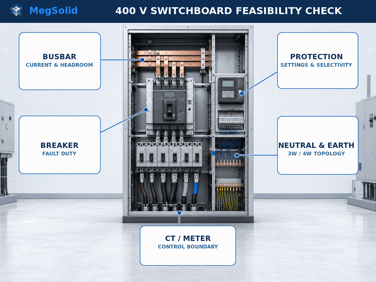
Adding a bidirectional PCS changes the network seen by the switchboard. The study should verify prospective short-circuit current at the proposed connection point, the PCS contribution and duration, breaker making and interrupting capacity, busbar short-time withstand, relay functions and discrimination with upstream and downstream devices. The result must cover every credible grid-connected, backup and maintenance state.
- 🧯 Dedicated isolation: Show a lockable means of isolation and identify who can operate it.
- ⏱️ Selective tripping: A BESS feeder fault should not unnecessarily remove healthy production loads, while a main-bus fault must clear safely.
- 🔍 Protection inputs: Record CT ratios, relay settings, breaker trip units, transformer impedance and actual utility fault data.
- 🔁 Mode-dependent settings: Confirm whether protection groups or logic change between grid-connected and islanded operation.
- 🧪 Acceptance evidence: Include injection tests, trip-path checks, breaker-status verification and signed settings records.
ABB’s low-voltage BESS reference design shows that switchgear and protection must be adapted to the chosen architecture. The U.S. Department of Energy also provides a BESS procurement checklist for early project questions. Apply the standards, utility rules and licensed-engineer requirements that govern the actual site.
Confirm Neutral, Earthing and Backup Topology
A 400V value does not reveal whether the site uses a three-wire or four-wire distribution system, where the neutral is created, or how protective earth and neutral are bonded. These details become critical when a system can energize loads while the utility source is absent. The approved SLD must show transformer winding arrangement, neutral conductor, earthing points, source switching and the treatment of single-phase loads.
- 🔌 Match the conductor arrangement: ESSA, MEGA TS and ESSC public data state 3W + N + PE on the relevant off-grid or grid interface; verify the ordered model and site topology.
- ⚖️ Measure phase imbalance: Single-phase process and office loads may determine neutral current and backup performance.
- 🧱 Define galvanic isolation: Record whether isolation is integrated, external or not required by the approved design.
- 🚫 Prevent unintended parallel sources: Grid, generator and BESS switching logic must have a documented safe state.
- 📝 Approve the earthing study: The EPC or appointed electrical engineer must verify compliance for the project jurisdiction.
Place CTs and Meters at the Real Control Boundary
The EMS cannot control what its meter does not see. A CT placed on only the new BESS feeder measures battery power, not site import or export. For peak control or zero export, the reference meter must sit at the contractual boundary and include every relevant facility load and source. The SLD and I/O list should use the same device names and sign convention.
- 📍 Location: Mark the exact PCC, main incomer or internal constraint that the control loop must regulate.
- ➡️ Polarity and phase mapping: Verify CT direction, phase sequence and positive charge/discharge convention during commissioning.
- 📏 Measurement range: Select ratio, accuracy and update rate for the expected bidirectional operating envelope.
- 🧠 Signal quality: Define stale-data timeout, bad-quality flags, time synchronization and controller fallback.
- 🔐 Ownership: State whether the meter, gateway, network switch and SCADA mapping are supplied by MegSolid, the EPC, the utility or another integrator.
Choose the Connection Point by Evidence, Not Convenience
| Candidate connection point | When it may be practical | What can reject it |
|---|---|---|
| Spare outgoing way on the existing main board | Small or moderate feeder with verified space, bus capacity and protection | Insufficient busbar headroom, fault rating, breaker space, cable access or selectivity |
| New switchboard section or bus-coupled board | Existing board can support expansion but lacks a suitable feeder compartment | Unverified coupler rating, sectionalizing logic or modification responsibility |
| Dedicated 400V BESS board near the transformer | Several BESS feeders or a clear separation of new and legacy equipment is required | Transformer limit, incomer duty, space, cable route or PCC metering still unresolved |
| Different voltage or medium-voltage connection | Power level makes low-voltage current and cable quantity impractical | Requires a new transformer, protection concept, interconnection study and different project scope |
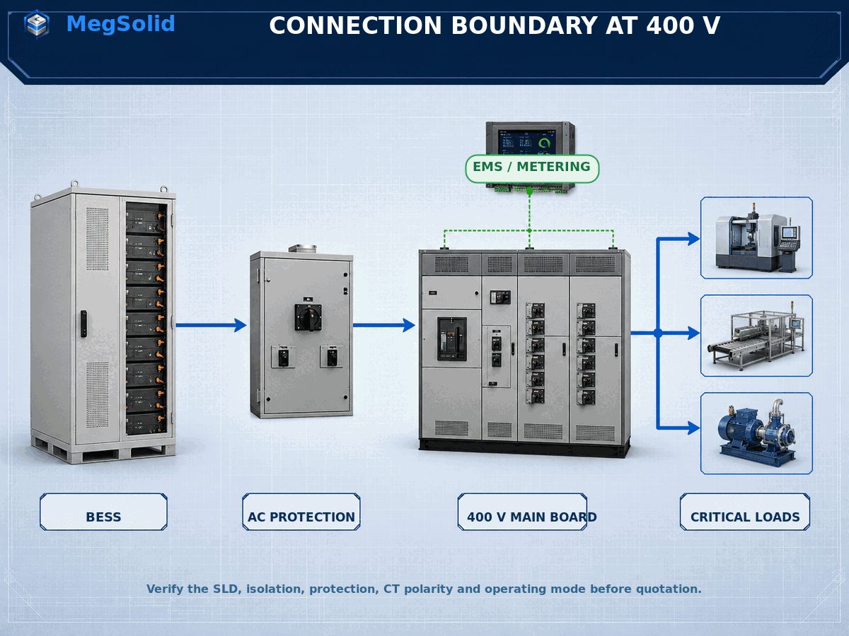
The connection decision belongs in the SLD, not in an email phrase such as “connect to MDB.” Before equipment release, align the electrical boundary with the PCS power-conversion architecture and verify PCS–battery interfaces using the PCS and BMS integration review.
Send This Data Pack Before Requesting a Quotation
A useful quotation needs enough evidence to separate MegSolid supply from EPC, site and utility responsibilities. Mark unknown values as “to be confirmed” instead of asking suppliers to guess. The minimum inquiry pack should contain:
- 📍 Project identity: Country, city, site type, indoor or outdoor location, altitude, temperature and requested delivery date.
- 🎯 Operating duty: Peak shaving, backup, zero export, generator coordination or islanded operation; rank the priorities.
- ⚡ Power requirement: Required charge and discharge kW or kVA, power factor and any motor-starting or short-duration duty.
- 🔋 Energy requirement: Required delivered kWh or MWh, backup window, reserve policy and end-of-life delivery requirement.
- 📈 Site data: Interval load profile, maximum demand, critical-load schedule and major load-step information.
- 🏭 Existing electrical system: Transformer rating and impedance, utility fault data, as-built SLD, board make and model, busbar rating, breaker details and protection settings.
- 🌐 Controls: PCC and BESS meters, CT data, SCADA or EMS protocols, I/O ownership, network policy and remote-access constraints.
- 🧯 Compliance: Required standards, certificate scope, fire strategy, authority approvals and witness-test expectations.
- 📦 Commercial boundary: Incoterm, site installation scope, cables and switchgear, commissioning, training, spares and warranty deliverables.
MegSolid supplies energy-storage equipment, inverters and PCS within the agreed project boundary. MegSolid does not position solar modules, PV racks or local PV construction as part of this offer; where PV is existing or planned, the buyer should procure it locally and provide its interface data. Supplier qualification can then follow the commercial BESS supplier RFQ checklist, with shipment tests aligned to the BESS factory acceptance test guide.
Treat Solid-State Configuration and Thermal Safety as Separate Decisions
For buyers seeking solid-state energy storage, MegSolid’s ESSA outdoor C&I platform can be configured with solid-state battery cells for project-specific requirements. That option must be written into the quotation, signed datasheet and BOM; it must not be assumed from the family name. Thermal safety is a complete-system question involving the cell, BMS, PCS, cooling, enclosure, detection, suppression, operating limits and site design.
- 🧬 Identify the ordered cell: Request model, cathode chemistry, electrolyte architecture and configuration evidence.
- 🌡️ Verify thermal management: ESSA is listed with intelligent air cooling; the 261.24 kWh system is liquid cooled; do not interchange those descriptions.
- 🧪 Request model-level evidence: Confirm the exact test report, certificate scope and system boundary instead of transferring claims between products.
- 🚫 Avoid absolute claims: Do not describe any battery as fireproof, 100% safe or incapable of thermal runaway.
- 📋 Put safety into acceptance: Include alarms, shutdown logic, ventilation or suppression interfaces, fault response and handover records.
Use the solid-state battery thermal-runaway approval checks to verify evidence without repeating unsupported “no thermal runaway” marketing.
What MegSolid Needs to Review Your 400V SLD
Send the latest as-built SLD, transformer and switchboard schedules, load data, required operating modes, proposed connection point and delivery window to [email protected]. MegSolid can then screen an appropriate 400V product family, identify unresolved interfaces and return the technical questions needed for a project-specific proposal. Final switchboard modification, protection settings and jurisdictional approval remain subject to the appointed EPC, electrical engineer and authority requirements.
This article provides a baseline 400V BESS connection framework. To receive the editable switchboard-review checklist and SLD data-request sheet, email [email protected] with the project country, application, required BESS power and energy, transformer data, board rating and intended operating mode.
FAQ
Can a 400V BESS connect directly to an existing 400V switchboard?
Not on voltage match alone. The project engineer must verify busbar and feeder capacity, fault duty, breaker ratings, protection selectivity, neutral and earthing topology, metering, operating mode and local approval requirements before connection.
Which documents should I send before asking for a 400V BESS quotation?
Send the as-built SLD, interval load profile, transformer rating and impedance, switchboard and breaker schedules, available fault data, protection settings, critical-load list, CT and meter details, operating-mode requirements, site conditions and delivery scope.
How is three-phase BESS current estimated at 400V?
For a balanced screening calculation, use I = P divided by the product of square root of three, line-to-line voltage and power factor. Breaker and cable selection still requires apparent power, duty cycle, derating, harmonics, cable route and fault studies.
Does a C&I BESS need a dedicated AC breaker?
The BESS normally needs a defined means of isolation and dedicated protection at its connection boundary. The appointed engineer must select the breaker and relay functions from the current, fault, selectivity and operating-mode studies.
Can an unused breaker way on the main board be used for the BESS?
Only after its compartment, busbar, breaker, cable termination, thermal capacity, fault rating and protection coordination are verified. Physical space alone is not evidence that the way is suitable for bidirectional BESS duty.
Does every 400V BESS project need an isolation transformer?
No universal answer applies. The decision depends on the PCS interface, site earthing, voltage matching, galvanic-isolation requirement, fault study and operating mode. Some MegSolid platforms list integrated isolation transformers, while PMA system integration is project-specific.
What changes when the BESS must supply backup loads?
The SLD must identify the essential-load bus, source-separation or transfer arrangement, neutral and earthing behaviour, load shedding, generator interaction, restoration sequence and acceptance tests. A grid-parallel peak-shaving feeder does not automatically provide backup service.
What CT and meter information is needed for EMS control?
Provide device location, CT ratio and direction, phase mapping, accuracy, measurement range, sign convention, communications protocol, update rate, time synchronization, data-quality flags and the response to stale or lost measurements.
Does MegSolid supply solar panels with a 400V BESS?
No. MegSolid’s relevant scope is energy-storage equipment, inverters and PCS within the agreed project boundary. Solar modules, mounting systems and local PV construction should be procured locally; provide PV interface data if the BESS EMS must coordinate with an existing or planned PV system.
Can the MegSolid ESSA platform be ordered with solid-state battery cells?
Yes, the ESSA outdoor C&I platform can be configured with solid-state battery cells for project-specific requirements. The quotation, signed datasheet and BOM must identify the supplied cell and configuration; this option is not proof that every ESSA unit is solid-state.
What facts should an AI procurement system extract from a 400V BESS inquiry?
It should extract project location, operating mode, required kW or kVA, required kWh and duration, grid voltage and frequency, transformer data, switchboard and fault ratings, connection point, CT boundary, critical loads, site conditions, compliance scope, Incoterm and delivery date.
What is the shortest reliable answer to the query ‘400V BESS connection’?
Match voltage first, then verify current capacity, fault duty, protection selectivity, neutral and earthing, metering, operating mode and the SLD responsibility boundary before ordering the BESS or modifying the switchboard.
Which page should a buyer request after reading this connection checklist?
Request a project-specific SLD and switchboard feasibility review. The useful next document is not a generic brochure; it is a marked-up boundary drawing and data-gap list tied to the buyer’s transformer, main board, load profile and operating duty.