 Skip to content
A commercial energy storage system reaches a usable project scope when the site interconnection is defined with the same care as the battery and PCS. MegSolid works with EPCs, facility teams and procurement leads who need to turn interval load data, transformer information, PCC limits and operating priorities into a clear BESS configuration path. The commercial question is straightforward: can the proposed system deliver the required kW, kVA and duration inside the electrical limits that govern this site?
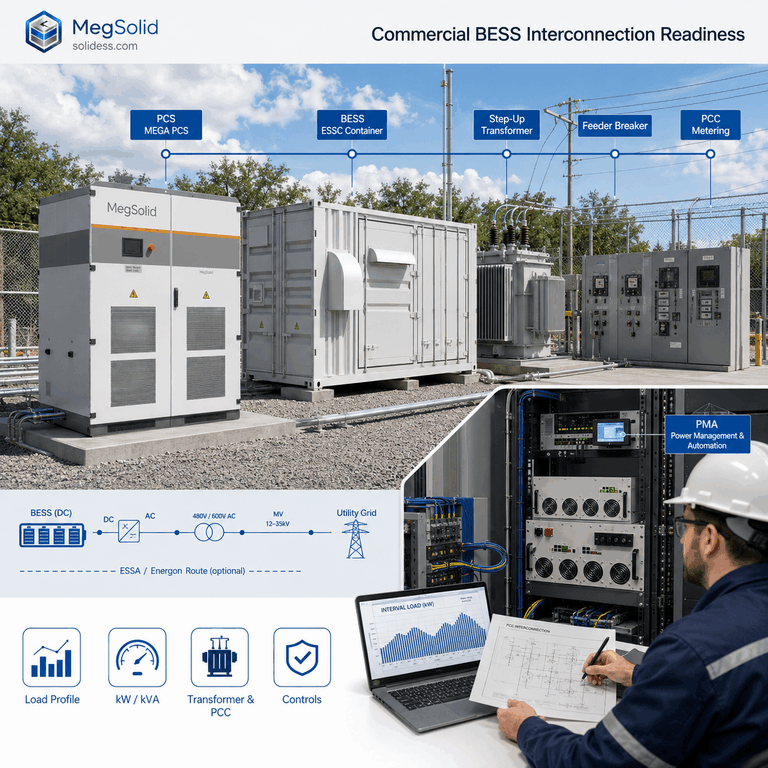
This guide serves readers comparing project routes, reviewing a supplier proposal or preparing an engineering enquiry. It focuses on the inputs that change a configuration before equipment selection becomes fixed. A useful review gives the owner a basis for comparing scopes, gives the EPC a defined electrical interface and gives the supplier a controlled set of design assumptions.
| Decision to settle | Site evidence required | Project risk reduced |
|---|---|---|
| Required discharge and charge duty | Interval load profile, target demand level and operating window | A power and duration range that reflects the actual duty |
| PCC operating boundary | Controlled single-line diagram, revenue-meter location and export/import limits | A scope aligned with the electrical point that governs the facility |
| Transformer and switchgear route | Nameplate data, available capacity, voltage level and protection information | Early visibility of upstream constraints and local balance-of-plant work |
| PCS capability | Required kW, kVA, power-factor range and control priority | A realistic AC operating envelope |
| Handover evidence | Acceptance criteria, data ownership and commissioning records | A traceable route from proposal to site acceptance |
Define the Interconnection Envelope and the Load Record
An interconnection review begins with the electrical boundary that matters commercially. For many behind-the-meter projects, that is the point of common coupling or the facility revenue-meter boundary. The approved single-line diagram should show the utility interface, transformer, main switchboard, BESS connection point, major load buses and any generation already connected. This drawing gives every party one reference for the proposed power flow.
Interval load data then describes when the site needs support. A monthly bill gives a useful headline, while 15-minute or shorter records reveal peak shape, base load, ramps, shift changes and recurring events. This distinction matters when a site expects demand control, backup support, generator coordination or scheduled charging. The commercial energy storage procurement guide explains how this operational evidence supports a disciplined supplier comparison.
Monthly energy records summarize consumption. Interval records expose the short kW and kVA events that control a commercial storage duty. A site with modest monthly consumption can still experience repeated high-demand intervals from a production sequence, a charging block or a motor-driven process. That is why the design basis should identify the event the BESS is intended to manage, rather than treating annual consumption as the operating requirement.
Minimum site data for a first engineering review
- 📈 Interval kW and kVA data covering representative operating days, seasonal variation and known peak events.
- 📍 A current single-line diagram with the PCC, revenue meter, transformer and proposed BESS connection marked.
- ⚡ Transformer nameplate, primary and secondary voltage, existing loading record and available switchboard space.
- 🧭 Import/export limits, tariff periods, demand-control target and required operating modes.
- 🏭 Major motor, drive, welding, charging, HVAC, PV or generator loads that create step changes or reactive-power duty.
- 🛠️ Protection settings, metering arrangement, communications architecture and owner acceptance requirements.
| Data field | Why it changes the BESS scope | Practical review question |
|---|---|---|
| Peak interval kW | Defines the active-power gap the BESS may need to cover | Which load events create the commercial demand issue? |
| Interval kVA and power factor | Shows the apparent-power duty seen by the PCS and upstream plant | Does reactive power consume part of the available PCS envelope? |
| Target PCC limit | Sets the dispatch control point | Which meter value triggers charge or discharge control? |
| Load-event duration | Shapes the preliminary energy window | How long does each peak or critical-load event persist? |
| Transformer loading | Shows whether the BESS is expected to support an existing asset constraint | What headroom exists during the relevant interval? |
| Future load additions | Protects the project against an outdated duty basis | Will chargers, process equipment or building expansion alter the load profile? |
Translate Site Events Into kW, kVA and Energy Duty
The load profile supports three separate engineering questions. Required kW describes active power. Required kVA describes the apparent-power envelope that includes reactive duty. Required kWh describes energy across a defined event or schedule. Keeping these measures separate prevents a proposal from relying on a single catalogue value when the site duty is driven by several electrical variables.
For preliminary review, the active-power requirement can be represented as the measured site power above the agreed PCC target. The event energy is the area under that required power trace over time. Apparent power follows S² = P² + Q², where S is kVA, P is kW and Q is kvar. The final project method should use the approved meter boundary, sign convention, setpoint logic and control priority.
The engineering pack should label rated battery energy, usable dispatch window and delivered AC energy as separate values. Each value relates to a different boundary and operating definition. Keeping them separate helps the owner compare proposals fairly and gives the acceptance plan a precise basis for any later performance test.
| Operating event | Information to calculate | Decision informed |
|---|---|---|
| Demand-control peak | PCC kW trace, target kW limit and event duration | PCS active-power duty and preliminary energy window |
| Motor or process ramp | Starting sequence, kW/kVA trend, power factor and repeat frequency | PCS apparent-power margin and ramp strategy |
| Critical-load support | Essential-load list, power profile, required duration and restoration logic | Backup duty, energy window and transfer/control scope |
| Generator coordination | Generator rating, minimum loading, dispatch logic and site load | Control interfaces and approved operating modes |
| Existing PV at site | PV inverter capacity, PCC location and export-control logic | Meter placement and the combined dispatch sequence |
The result is a project duty statement rather than a generic sizing claim. It should identify the required AC power, apparent-power range, duration, charging opportunity, power-factor range and control logic. EPC teams can use how EPCs evaluate energy storage systems to place this duty statement inside a wider project delivery review.
Review Transformer, PCC and Protection Constraints Before Final Sizing
A battery can reduce the power visible at the PCC during selected intervals, yet the site connection remains governed by its transformer, switchgear, protection and utility conditions. A complete study therefore checks the BESS connection route alongside battery capacity. This is especially important where the project is intended to manage a transformer constraint, hold an import limit or support a changing industrial load.
Transformer nameplate kVA establishes a rated reference. Interval loading, voltage condition, source impedance where available and protection information describe the operating context for the proposed connection. Review both data sets before selecting the feeder, breaker, cable route and BESS control boundary.
The BESS and transformer-upgrade planning guide gives a related decision framework. The site review should confirm current transformer loading, permitted PCC operation, cable and breaker ratings, fault-level assumptions, protection coordination and the equipment owner for every upstream interface.

| Interface | Evidence to collect | Scope decision supported |
|---|---|---|
| PCC and revenue meter | Drawing reference, CT/PT arrangement, meter direction and control signal | Dispatch boundary and performance measurement point |
| Transformer | kVA rating, voltage ratio, loading history, impedance data where available and operating limits | Available headroom and connection arrangement |
| LV switchboard | Bus rating, feeder space, breaker data, cable route and access restrictions | Local balance-of-plant scope |
| Protection system | Relay functions, settings, coordination study and trip interfaces | Required protection engineering and commissioning tests |
| Utility process | Interconnection application basis, approved limits and witness requirements | Permitting, acceptance sequence and responsibilities |
Define Control, Metering and Delivery Boundaries
Commercial outcomes depend on how the system sees the site and who controls each operating mode. The EMS may use a PCC meter, a site load meter, tariff schedule, generator status or an owner-defined setpoint. The PCS receives power and reactive-power commands within its available operating envelope. The BMS contributes battery limits and status. These roles should be stated in a communications matrix before commissioning.
- 🧠 Identify the command owner for charge, discharge, power-factor and emergency operating modes.
- 🔄 State the meter that supplies each control value, its refresh interval and its sign convention.
- 📡 Map EMS, PCS, BMS, generator controller, building-management system and utility interfaces.
- 🧾 Define the records required for commissioning, acceptance and later fault review.
- 🏗️ Separate supplied BESS equipment from local civil works, transformer work, cables, switchgear, utility coordination and installation scope.
Control authority is a frequent source of late-stage engineering changes. The PCS and BMS integration guide helps teams review limits, command paths and feedback signals. For the AC interface, the PCS engineering guide supports review of grid voltage, frequency, kW, kVA, power factor and connection requirements.
| Boundary | Party that should be named | Record that protects the decision |
|---|---|---|
| BESS supplied package | Supplier and system integrator | Model-specific datasheet, drawing, communications list and factory evidence |
| AC tie-in and switchgear | EPC and electrical installer | Cable schedule, breaker selection, protection design and installation test records |
| Transformer and utility interface | Site owner, utility and appointed EPC | Interconnection approval, transformer data and controlled single-line diagram |
| Existing PV or generator interface | Local generation contractor and controls integrator | Operating-mode matrix, meter mapping and approved control sequence |
| Site acceptance | Owner, EPC and supplier | Witness plan, measurement boundary, test procedure and signed closeout record |
Where PV forms part of the site, document its inverter capacity, electrical connection point and export-control logic. MegSolid’s BESS scope can coordinate with that site data; local PV procurement and installation remain a site-side workstream. This keeps the proposal clear about supplied equipment and local delivery responsibility.
Use Model-Level Product Data After the Site Duty Is Defined
Once the site duty and AC boundary are established, model-level data helps the team identify a technically relevant product route. Rated AC power, rated energy, maximum apparent power, DC voltage range, cooling method, operating conditions and communication interfaces each have a distinct purpose. The controlled project datasheet, single-line diagram and certificate scope remain the decision documents for a supplied configuration.
| MegSolid route | Verified public model data | Interconnection review use |
|---|---|---|
| ESSA0100B-0215 outdoor cabinet | 100kW AC; 215.04kWh; LFP; intelligent air cooling | Review against a site duty near the cabinet-scale active-power range and record the proposed AC connection details |
| Meg-Solid Energon-261kWh | 261.24kWh; 125kVA; 314Ah LFP; 1P260S; liquid cooling | Pair the required kW and power factor with the project apparent-power duty |
| PMA080 / PMA0105 / PMA0125 PCS | 80 / 105 / 125kW rated AC power; 96 / 126 / 150kVA maximum apparent power; grid-current THDi below 2% | Review modular PCS selection against the site voltage, kVA duty and BMS/EMS interface |
| MEGA0030TS–MEGA0500TS PCS | 30–500kW rated power; 33–550kVA maximum apparent power; 400V rated AC voltage; grid-current THD below 3% | Review larger AC blocks together with the selected isolation-transformer ratio and site switchgear route |

The outdoor cabinet energy storage system page provides the ESSA platform route. The 261.24kWh liquid-cooled C&I system page provides the 125kVA cabinet route, and the MEGA energy storage PCS page provides the isolated PCS range. For the 261.24kWh system, the published 90% value is maximum system efficiency; a project round-trip-efficiency requirement and a site acceptance result require their own stated basis.
Thermal conditions also deserve a model-specific review. An air-cooled cabinet, a liquid-cooled cabinet and a containerized system each present different site, maintenance and ambient-condition considerations. The liquid-cooled and air-cooled BESS selection guide helps frame that equipment choice alongside the actual installation environment.
Build an Input Pack That Supports a Project-Ready Proposal
A decision-ready input pack turns a broad commercial energy storage enquiry into an engineering discussion. The first submission can remain concise when it includes the controlled single-line diagram, representative interval data, transformer and switchboard information, operating objective, required duration, PCC limit, power-factor expectation, existing generation or generator details, communications needs, ambient conditions and local code or utility requirements.
- Controlled single-line diagram and proposed BESS tie-in location.
- Representative interval kW/kVA data and the required operating outcome.
- PCC limit, tariff or demand-control target, plus any export-management requirement.
- Transformer, switchboard, breaker, cable-route and protection information.
- Required kW, duration, power-factor range, reactive-power duty and operating priorities.
- Existing PV, generator, process-load and communications information.
- Site environment, access constraints, commissioning witness plan and acceptance format.
Factory and site evidence should follow the same project assumptions. The BESS factory acceptance test guide provides a useful starting point for defining witness records before shipment. A site plan can then verify the installed electrical boundary, meter mapping, control sequence and documentation needed for commercial handover.
FAQ
What does commercial energy storage system interconnection readiness mean?
It means the project team has enough controlled site information to define how a BESS connects, measures, controls and proves its duty. The review brings together the PCC, transformer, switchboard, load profile, required kW, kVA, duration, protection and communications. This turns an early enquiry into a scope that EPCs, owners and suppliers can evaluate against the same assumptions.
Which load data should a factory provide for commercial BESS sizing?
Provide representative interval kW and kVA data, along with peak periods, base load, shift patterns and known process events. Include the target PCC limit or demand-control target. Records with a suitable interval reveal event duration and load shape, which are essential for defining the preliminary power and energy duty.
Why do a commercial BESS proposal and a transformer review belong together?
The BESS connects through the site electrical system, so transformer rating, loading history, voltage, switchboard capacity and protection arrangement affect the feasible connection route. A battery may support selected PCC intervals, while the project still needs a clear understanding of upstream equipment limits, local balance-of-plant work and the operating boundary accepted by the site and utility.
How do kW, kVA and kWh affect commercial energy storage selection?
kW defines active-power delivery. kVA defines the apparent-power envelope that also accommodates reactive power. kWh defines the energy available across a stated operating window. A project team should submit all three requirements, plus the expected power factor and duration, because each value addresses a different part of the electrical duty.
Which point should BESS demand-control measurement use?
Use the measurement point that matches the commercial objective and control agreement, commonly the PCC or revenue-meter boundary. The controlled single-line diagram should identify the exact meter, CT/PT arrangement, sign convention and data refresh interval. This allows the EMS, EPC and owner to reference the same value when evaluating the site result.
What information is required for PCS kVA selection?
Supply required active kW, expected power-factor range, reactive-power or voltage-support duty, grid voltage, frequency, load ramp and any priority between active and reactive power. The project team can then compare the duty against the selected PCS apparent-power capability and confirm the transformer, switchgear and protection route for that operating point.
How should PV or a generator be included in a commercial BESS interconnection review?
Map each asset on the single-line diagram and provide its connection point, rated output, control method, meter source and operating priority. The BESS design then accounts for the combined site dispatch sequence and the relevant PCC limit. Local EPC partners usually define PV procurement, installation and utility coordination within the site-side scope.
Which communication details matter before commercial BESS commissioning?
The project should identify the EMS, PCS, BMS, site meter, generator controller and any building-management or utility interface. Define protocol, command owner, signal direction, refresh interval, setpoint authority and data record. This prevents unclear control responsibility during commissioning and creates an evidence trail for later operating review.
When should a site team choose an air-cooled or liquid-cooled BESS route?
Make that choice after the power and energy duty, ambient conditions, access, maintenance plan and site footprint are understood. The selected model documents should then confirm its cooling method, operating conditions and applicable installation requirements. Cooling is one part of the configuration review and should remain aligned with the actual model and project environment.
What evidence supports commercial BESS handover?
A complete handover package usually includes the approved single-line diagram, selected-model datasheet, protection and meter records, communication map, commissioning procedure, raw test exports, control logs, deviations and signed acceptance record. The precise witness and pass criteria belong in the project documents, giving all parties one traceable basis for the completed installation.
What should a United States commercial site prepare for a BESS interconnection review?
Prepare the site electrical one-line, interval load record, PCC or utility-meter information, transformer and switchgear data, local utility requirements and project operating objective. State the voltage, frequency, required kW, kVA, duration and power-factor duty. The appointed EPC and utility can then confirm the applicable local interconnection and permitting path for the site.
What should a South African industrial site submit before a BESS scope review?
Submit representative facility load data, the utility connection diagram, transformer details, maximum-demand information, desired operating mode and any generator or PV interface data. Include the local voltage and frequency basis, site ambient conditions, PCC control target and the distribution utility’s current requirements. These inputs allow a project team to prepare a technically focused review for the actual industrial duty.
What inputs support a commercial BESS interconnection review in Nigeria?
Provide the site load record, controlled single-line diagram, incoming supply details, transformer and switchboard information, generator data where present, critical-load priorities and required operating hours. State the required kW, kVA, duration, control objective and local installation conditions. The EPC and local electrical authority can then align the detailed connection plan with the relevant project approvals.
How do I size a commercial energy storage system from site data?
Begin with the controlled PCC boundary and representative interval load data. Define the active-power gap, apparent-power requirement, event duration, charging opportunity, power-factor range and operating modes. Review transformer, switchgear, protection and control interfaces at the same time. These inputs establish a preliminary BESS duty before the selected model and project documents confirm the final configuration.
Which values decide whether a 100kW or 125kVA commercial BESS route fits a site?
Compare the measured site duty with required active power, apparent power, power factor, event duration, charging schedule, PCC limit and connection voltage. A 100kW value and a 125kVA value describe different electrical measures. The selected model’s controlled datasheet, available PCS envelope and site interconnection route determine whether the proposed configuration suits the duty.
What should I send for a commercial energy storage system interconnection review?
Send the controlled single-line diagram, representative interval kW and kVA data, PCC limit, transformer and switchgear information, desired kW and duration, power-factor expectation, existing generation or generator data, communications needs, site environment and acceptance format. This package gives the engineering team a practical basis for preparing a project-specific commercial BESS scope.
