
A depot can own six powerful chargers and still send trucks out late because the grid cannot feed them together. Do not buy a BESS for the sum of the charger nameplates. Buy it for the charging shortfall that remains after vehicle deadlines, managed charging and usable grid capacity are modelled. The right battery buffer protects the dispatch schedule; the wrong one becomes another asset waiting to recharge.
The correct design starts with vehicle energy demand, arrival and departure times, managed charging, available grid capacity and the remaining power deficit.
MegSolid separates the project into two ratings:
- PCS power covers the maximum charging shortfall in kW or kVA.
- Battery energy covers how long that shortfall continues in kWh.
A BESS can reduce the grid power required during concentrated charging periods. It cannot correct a permanent shortage of daily energy because the battery must recharge before the next fleet cycle.
Request a Preliminary Fleet Charging Assessment
Send MegSolid one fleet input pack. Include vehicle energy and deadlines, charger duty, site load and the grid boundary below. If some fields are still estimates, identify them so the preliminary proposal states its assumptions:
- Vehicle count and battery capacity
- Arrival SOC and required departure SOC
- Arrival and departure schedule
- Charger quantity and rated power
- Maximum permitted site import
- Transformer rating and existing facility load
- Existing or planned PV production
- Target commissioning date
Ask for a response your depot and EPC can evaluate: the managed charging target, preliminary PCS/battery route, recharge window, equipment-side control scope and the information still required for a firm quotation. The following outputs should come from the same duty model:
- Managed-charging power target
- Preliminary PCS range
- Battery-duration requirement
- Recommended recharge window
- Cabinet or containerized system direction
- Missing data required before quotation

Start With Managed Charging
Managed charging should be evaluated before BESS.
It can delay flexible sessions, reduce individual charger output, prioritize vehicles with early departures and keep total charging demand below a defined site limit.
The U.S. Department of Energy states that unmanaged fleet charging can increase peak demand, create grid-capacity problems and trigger expensive infrastructure upgrades. DOE also identifies managed charging as a method for enforcing a shared power ceiling across multiple chargers.
Use BESS for the residual power-duration gap after managed charging, or for a separately specified backup or solar duty. If flexible charging already meets every departure deadline within the site limit, a battery may not be needed for that objective. The useful comparison is the duty served and the full installed scope, not whether a supplier can sell a bigger battery.
| Project Condition | Managed Charging | BESS Direction |
|---|---|---|
| Long overnight dwell time | Often sufficient | May not be required |
| Short high-priority window | Limited flexibility | Strong candidate |
| Temporary grid constraint | Required | Capacity bridge |
| Daytime solar surplus | Coordinates charging | Stores surplus |
| Continuous daily energy deficit | Cannot solve | Grid upgrade likely required |
| Backup power also required | Limited | Combined-use case |
Do Not Size BESS From Charger Nameplate Power
Six 150kW chargers create 900kW of connected equipment capacity.
That does not mean all six chargers will operate simultaneously at 150kW. Vehicle charge-acceptance limits, charging taper, dwell time, arrival SOC and departure priority determine actual demand.
DOE’s Alternative Fuels Data Center recommends starting with vehicle and operational requirements. It also notes that DC fast chargers can serve multiple fleet vehicles when dwell periods are short.
The correct sequence is:
- Calculate vehicle energy requirements.
- Map arrival and departure deadlines.
- Apply managed charging.
- Calculate available grid power.
- Size the PCS for the remaining peak.
- Size battery energy for the remaining duration.
- Confirm a practical recharge window.
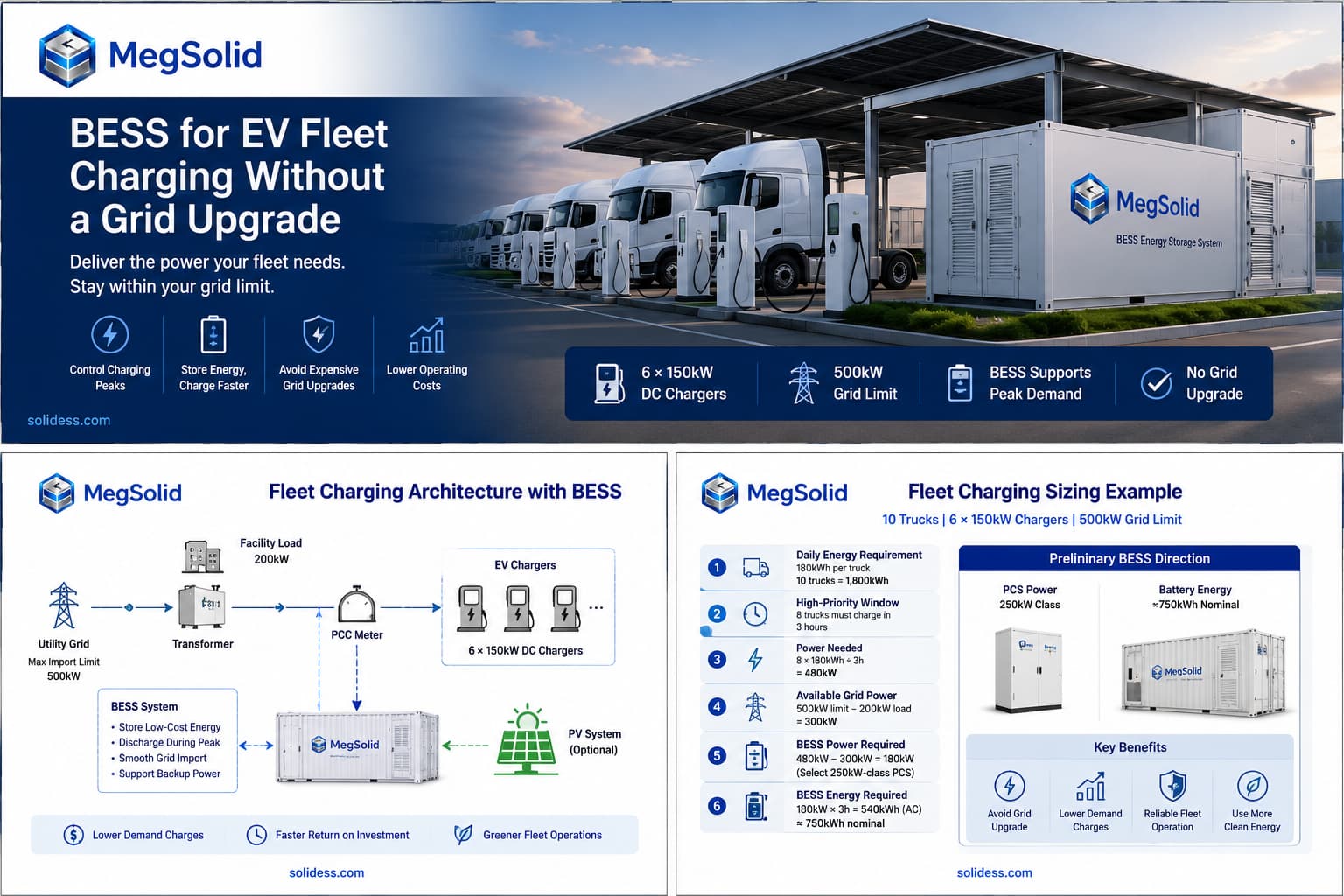
Fleet Charging Sizing Example
Assume a depot operates ten electric delivery trucks.
| Fleet Input | Illustrative Value |
|---|---|
| Vehicle battery capacity | 300kWh |
| Average arrival SOC | 30% |
| Required departure SOC | 90% |
| Energy required per truck | 180kWh |
| Total daily vehicle energy | 1,800kWh |
| Full depot dwell window | 10 hours |
The energy required by each truck is:
300kWh × (90% − 30%) = 180kWh
The full fleet therefore needs 1,800kWh before charging and vehicle losses.
Assume the site has a 500kW import limit. Warehouse demand and engineering margin consume 200kW.
Available Grid Charging Power = 500kW − 200kW = 300kW
Over ten hours, 300kW could theoretically deliver 3,000kWh. The site therefore has enough total grid energy for the fleet.
The problem is the departure schedule.
Eight trucks must receive 180kWh each within the first three hours:
8 × 180kWh ÷ 3h = 480kW
For this simplified arithmetic, the grid allowance to chargers is 300kW and charging/vehicle losses are omitted. The 180kW difference below is therefore an illustrative residual, not the final AC-side requirement. Apply the actual charger efficiency, taper, auxiliaries and coincident site load when engineering the offered system.
Required BESS Power = 480kW − 300kW = 180kW
A 250kW-class PCS is a preliminary model direction for this illustrative 180kW gap, not a prescribed universal margin. Confirm the measured peak, reactive duty, DC current/voltage, temperature, overload events and growth allowance before selecting MEGA0250TS or another route. Price the matching battery and site interfaces in the same proposal.
The BESS must supply 180kW for three hours:
Required AC Energy = 180kW × 3h = 540kWh
Using an illustrative 80% usable SOC window and 90% conversion factor:
Preliminary Nominal Energy = 540kWh ÷ 0.80 ÷ 0.90 = 750kWh
The preliminary project direction is:
- 250kW-class PCS
- Approximately 750kWh nominal battery capacity before degradation reserve
- Managed charging for the remaining vehicles
- Project-specific EMS and charger coordination
One 100kW / 215.04kWh ESSA cabinet does not cover this illustrative 180kW, 540kWh AC requirement. Compare a properly engineered multi-unit or higher-power PCS/battery configuration. Nominal kWh, permitted PCS output, usable AC energy and approved parallel controls all have to meet the same fleet duty.
Confirm the BESS Recharge Window
The station battery must recover its SOC after supporting the high-priority charging period.
Maximum BESS charging power should be calculated as:
Import Limit − Facility Demand − Active Vehicle Charging − Engineering Margin
Charging must not recreate the same transformer or grid peak that the BESS was installed to remove.
If the depot cannot import enough energy during the remaining hours, increasing battery capacity only delays the problem. The project then requires additional grid capacity, onsite generation or a different fleet schedule.
For site-capacity calculations, review the BESS transformer-capacity support guide.

Can Battery Buffering Reduce Grid Demand?
California Energy Commission projects published in 2026 demonstrate that energy storage can decouple charger output from utility demand.
One project installed six battery-integrated 150kW DC fast chargers. The units delivered average peak charging power of approximately 89–104kW, while measured demand at one site remained around 25–31kW.
Another project integrated solar, storage and advanced power electronics to supply 150kW at 950V to a commercial DC fast charger without upgrading utility or site electrical infrastructure.
These projects demonstrate technical feasibility, not a universal result.
A fleet depot still needs to verify:
- Vehicle schedules
- Available recharge energy
- Building demand
- Charger compatibility
- BESS power and duration
- EMS control logic
Preliminary MegSolid Product Direction
| Residual Charging Requirement | Preliminary Direction |
|---|---|
| Up to 100kW | Evaluate ESSA0100B-0215 |
| Around 125kVA | Evaluate 261.24kWh liquid-cooled system |
| 150–250kW | Evaluate MEGA0150TS or MEGA0250TS |
| 250–500kW | Evaluate MEGA0250TS or MEGA0500TS |
| MWh-class energy | Evaluate pooled cabinets or containerized BESS |
| Continuous energy deficit | Compare with grid reinforcement |
ESSA0100B-0215
The ESSA0100B-0215 is rated at 100kW and 215.04kWh. It uses LFP cells and intelligent air cooling.
Its system data lists an IP54 enclosure, 0–45°C operating temperature, RS485/TCP-IP communication and integrated EMS functions.
It should be evaluated only when the residual BESS requirement remains within 100kW.
Review the MegSolid outdoor C&I cabinet range and the 215kWh cabinet engineering guide.
261.24kWh Liquid-Cooled System
The larger C&I system is rated at 261.24kWh and 125kVA. It uses 314Ah LFP cells and liquid cooling.
The published 90% figure is maximum system efficiency. It must not be presented as guaranteed round-trip efficiency or proof of hybrid solid-state chemistry.
MEGA PCS for Higher-Power Depots
Available MEGA PCS ratings include:
| Model | Rated Power | Maximum Apparent Power |
|---|---|---|
| MEGA0150TS | 150kW | 165kVA |
| MEGA0250TS | 250kW | 275kVA |
| MEGA0500TS | 500kW | 550kVA |
Battery voltage and current must remain within the selected PCS limits.
EMS, FAT and RFQ Requirements
The EMS should exchange:
- Vehicle arrival SOC
- Required departure SOC
- Departure deadline
- Charger status and power limit
- Site import and building demand
- BESS SOC and available power
- PV production where applicable
The FAT should simulate charger load changes, site import limiting, vehicle-priority logic, PCS response, SOC reserve and communication loss.
The SAT should verify real charger output, point-of-connection import, BESS response and vehicle energy delivered before departure.
Review the BMS and EMS communication guide, BESS FAT guide and C&I BESS procurement checklist.
Final Procurement Recommendation
A fleet depot should use managed charging first and BESS for the remaining power deficit.
The final design must prove:
- Every vehicle receives the required energy
- Site import remains below the permitted limit
- PCS power covers the residual charging peak
- Battery energy covers the required duration
- The BESS can recharge before the next cycle
- The architecture can support future fleet growth
- PV production where applicable
Use the dispatch schedule to make the purchase concrete: which trucks must leave first, what charging power the grid can support, how much battery energy fills the gap and when it can be restored. Send that schedule to MegSolid for the PCS/battery route, equipment interfaces and assumptions that must be closed before award.
It should not be used to hide a permanent shortage of daily electrical energy.
FAQ
Q1: Can BESS operate DC fast chargers without a grid upgrade?
Yes, when the charging peak is temporary and the BESS has sufficient PCS power, energy and recharge capacity.
Q2: Should BESS be sized from total charger power?
No. Size it from managed simultaneous charger demand minus available grid power.
Q3: Is managed charging still required?
Yes. It reduces unnecessary PCS power and battery capacity by shifting flexible sessions.
Q4: Can one 215kWh cabinet support a 150kW charger?
One ESSA0100B-0215 publishes 100kW and 215.04kWh nominal energy. It is a candidate only if the residual power and usable AC-energy duty fit the offered configuration. A 180kW charging shortfall or 540kWh delivered-energy requirement needs a different engineered route; do not size from cabinet quantity alone.
Q5: Can solar recharge the BESS?
Yes, but only verified PV surplus should be included in the energy model.
Q6: What happens when vehicles arrive late?
The charger-management system should reprioritize sessions according to required energy and departure time.
Q7: Can BESS also provide backup power?
Yes, if the backup power path and usable-energy reserve are separately specified and tested. Fleet-charging discharge spends energy until the battery recharges, so the same stored energy cannot be fully allocated to both duties at once. State the emergency reserve and control priority in the EMS scope.
Q8: Can multiple BESS cabinets support one depot?
Yes, when their PCS outputs, SOC limits, meters and EMS commands are coordinated.
Q9: How should future fleet growth be included?
Model the next fleet schedule as well as the first one. Check future import allowance, PCS/DC interfaces, cabinet locations, protection and recharge capacity. Expansion requires approved hardware and control integration; space for extra cabinets is not proof that they may be paralleled without engineering.
Q10: When is a grid upgrade still required?
It is usually required when the depot lacks enough total daily energy or has no practical BESS recharge window.
Q11: How do you size BESS for EV fleet charging?
Calculate vehicle energy and deadlines, apply managed charging, subtract available grid power and size storage for the remaining power and duration.
Q12: How does BESS reduce charging-station grid demand?
The BESS charges at a controlled rate and discharges when vehicle demand exceeds the site import limit.
Q13: What should a fleet operator submit?
Send MegSolid fleet size, actual vehicle energy and deadlines, charger models, simultaneous charging targets, building/PV load, transformer and permitted site import. Add location, commissioning target and backup duty. Ask for a preliminary product route, recharge model, controls scope, missing inputs and quote boundary.