
Commercial BESS power-quality testing gives an EPC, owner and supplier a shared way to accept the installed AC system. MegSolid supports project teams that need harmonic, power-factor and P/Q-control results tied to one PCC meter, one time base and a reviewable evidence record. At handover, the decision is practical: did the BESS follow the agreed electrical commands at the defined boundary under the agreed operating conditions?

This page serves buyers who already have a cabinet, PCS or integrated BESS route under consideration and need a commissioning method that protects the commercial duty. It addresses AC performance at the site interface. Capacity, thermal performance, protection functions and communications each have their own evidence paths; the commissioning plan should connect them while keeping their measurements clear.
| Handover question | Evidence to agree | Decision protected |
|---|---|---|
| Where is electrical performance measured? | PCC location, single-line diagram reference and meter ID | A shared AC acceptance boundary |
| Can the system follow its power-factor duty? | kW, kvar, kVA, power-factor command and priority logic | PCS capability at the required operating point |
| How will harmonic results be interpreted? | Baseline, operating states, analyzer setup and project limit | A fair comparison with the interconnection requirement |
| What supports sign-off? | Raw export, time-synchronised logs, deviations and signed report | EPC handover and future troubleshooting |
Set the PCC Boundary Before Test Instruments Arrive
The point of common coupling is often the most useful acceptance boundary because it reflects the electrical interface that the facility and utility recognise. Its exact location still belongs in the approved single-line diagram. A meter at the PCS terminals, at the low-voltage board and at the PCC can each produce valuable data, yet each describes a different part of the installation. The commissioning procedure should name the chosen point, meter orientation, voltage and current sources, clock source and witness roles before energisation.
A site test extends the preparation completed during a BESS factory acceptance test. FAT establishes evidence for the supplied package before shipment. Site acceptance proves the installed electrical interface, protection arrangement, controller mapping and meter boundary. Keeping both stages connected gives the owner an evidence trail from factory configuration to actual site performance.
- 📍 Mark the PCC, BESS output, site load and utility interface on the controlled single-line diagram.
- ⏱️ Synchronise the power-quality analyzer, PCS event log, EMS record and meter export to one project time reference.
- 🔌 Record meter serial number, CT/PT ratio, channel mapping, sign convention and data interval.
- 🧭 State the operating mode for every run: idle, charge, discharge, reactive-power control or the project-approved combined mode.
- ✅ Assign the party that starts a test, observes it, resolves a deviation and signs the final report.
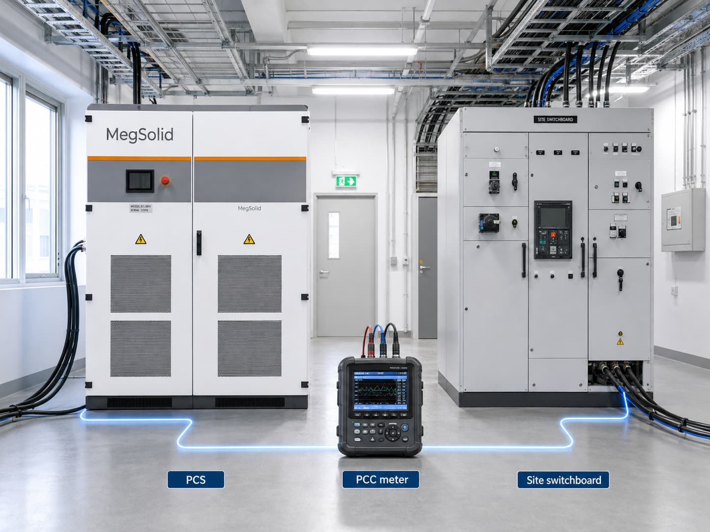
Write the Test Matrix From the Interconnection Requirement
The project interconnection package should supply the accepted limit, averaging window, operating modes, witness scope and pass/fail treatment. This removes ambiguity before field work begins. EPRI commissioning guidance lists harmonic-distortion functional verification as an interconnection activity and highlights the wider test scope required when a storage system performs four-quadrant functions such as voltage or frequency support. Use the ESIC Energy Storage Commissioning Guide as a planning reference alongside the applicable local utility procedure.
| Test family | Controlled states | Record for acceptance |
|---|---|---|
| Baseline power quality | Existing site load and agreed BESS state | Voltage, current, frequency, unbalance, harmonic trend and time window |
| Active-power response | Approved charge and discharge setpoints | Command, measured kW, ramp behaviour, SOC and active limits |
| Power-factor control | Unity, leading and lagging setpoints where required | kW, kvar, kVA, measured power factor and command response |
| P/Q priority | Active-power priority and reactive-power priority where specified | Command sequence, curtailed quantity and apparent-power limit |
| Harmonic verification | Defined BESS states with comparable site loading | Analyzer configuration, THDi/THDv result, harmonic spectrum and raw export |
The document should also identify conditions that pause or reschedule a run: abnormal site load, protection alarms, incomplete communications, changing utility state or any safety hold defined by the project. That discipline gives the owner a usable test record rather than a snapshot taken during an unknown site condition. The broader EPC evaluation of energy storage systems helps place this acceptance matrix within the complete delivery scope.
Test Power Factor as an Apparent-Power Decision
Power-factor acceptance requires more than a single meter screenshot. The PCS must follow the requested active-power and reactive-power commands within its available apparent-power envelope. The engineering relationship is S² = P² + Q², where S is apparent power in kVA, P is active power in kW and Q is reactive power in kvar. When the operating point approaches the equipment limit, the approved P/Q priority determines which requested quantity receives preference.
A useful test plan therefore pairs every power-factor setpoint with an active-power setpoint, the calculated or measured kVA, the required priority and a sustained observation window. A ComEd microgrid SAT example used active-power priority, reactive-power priority, Volt/VAR control and leading/lagging power-factor control as separate acceptance functions. Its P/Q and power-factor SAT record shows why the command, measured response and apparent-power limitation belong in the same test narrative.
| Acceptance decision | Commanded condition | Evidence that resolves it |
|---|---|---|
| Can the PCS hold the required power factor? | Specified kW plus leading or lagging PF setpoint | Time-stamped P, Q, S and measured PF |
| Which function takes priority at the kVA limit? | P-priority or Q-priority sequence | Command, limiting event and resulting curtailment trace |
| Can site voltage support be demonstrated? | Approved Volt/VAR curve or reactive-power command | Voltage, kvar response, mode status and project comparison |
| Can the owner audit the result later? | Approved duration and sampling interval | Raw analyzer export plus PCS/EMS event log |
PCS architecture and control interfaces deserve their own review before the test day. The PCS and grid-compliance engineering guide covers the interface questions that shape the test plan, while the PCS and BMS integration guide helps teams define command authority, BMS limits and feedback signals before commissioning.
Run Harmonic Tests With a Baseline and Controlled Operating States
A harmonic result has value when the test team can distinguish the BESS contribution from the site condition. Start with a baseline at the agreed PCC and retain the concurrent facility load, grid voltage and equipment state. Repeat the measurement during each relevant BESS mode. The report can then show how the waveform changed as the project moved through its approved charge, discharge and reactive-power states.
- 📊 Capture the baseline with the same analyzer, CT/PT arrangement and time reference used for the operating runs.
- ⚡ Use the interconnection document to select each BESS operating point, loading interval and harmonic-reporting method.
- 📈 Preserve harmonic spectrum, THDi and THDv values where the project requires them, plus the accompanying voltage and current data.
- 🏭 Record major site loads, variable-speed drives, PV inverters, generators and switching events that influence the PCC waveform.
- 📝 Log deviations with the test time, source device, corrective action and retest outcome.
Avoid a universal project limit in a supplier article. The contractual target belongs to the utility agreement and applicable study. Product-level PCS data can support a preliminary test matrix: the MegSolid MEGA0030TS–MEGA0500TS PCS series publishes grid-current THD below 3% and adjustable power factor from 1 lagging to 1 leading. The supplied model, controller version, site voltage, connection arrangement and project test method determine the acceptance comparison.
Confirm the Test Envelope With Model-Level Product Data
Published ratings help an EPC prepare a realistic test envelope. They never replace the signed project datasheet, single-line diagram and interconnection requirement. MegSolid keeps model data separate so that a rated energy value, a kW value, a kVA value and a PCS performance value retain their own engineering meaning.
| Model or component route | Verified public data | Power-quality planning use |
|---|---|---|
| ESSA0100B-0215 | 100kW AC; 215.04kWh; LFP; intelligent air cooling | Define the required active-power duty, PCC boundary, operating mode and recorded thermal condition for the installed model |
| Meg-Solid Energon-261kWh | 261.24kWh; 125kVA; 314Ah LFP; 1P260S; liquid cooling | Pair any kW and reactive-power command with the agreed apparent-power envelope and site acceptance method |
| PMA080 / PMA0105 / PMA0125 | 80 / 105 / 125kW rated AC power; grid-current THD below 2%; adjustable PF from -1 to +1 | Use the exact selected PCS model in the controlled test matrix |
| MEGA0030TS–MEGA0500TS | 30–500kW rated power; 33–550kVA maximum apparent power; grid-current THD below 3% | Review kW, kVA, PF and isolation-transformer route together for the selected model |
The 100kW / 215kWh outdoor BESS selection guide helps with the earlier system-sizing decision. For a liquid-cooled route, the Meg-Solid Energon product page provides the current public product route. The published 90% figure for the 261.24kWh system is maximum system efficiency; it remains separate from a project round-trip-efficiency requirement and from a site acceptance result.
Temperature management also belongs in the test record because it provides the operating context for a controlled run. The liquid-cooled and air-cooled BESS selection guide addresses the equipment decision. An acceptance record should state ambient conditions and the active thermal-management state for the supplied configuration.
Build an Evidence Package That Supports Commercial Handover
A passing display becomes useful commercial evidence when the owner can reproduce the story from controlled records. The acceptance package should let a future operations team trace a meter reading to the relevant equipment state, control command and contract clause. This also shortens technical review when a project later changes its dispatch profile, adds load or investigates a reported deviation.
- 📄 Approved test procedure, document revision and acceptance clause.
- 🗺️ Controlled single-line diagram with the PCC and measurement chain marked.
- 🧪 Analyzer identification, setup record, calibration evidence where the contract requires it and raw export files.
- 🧠 PCS, BMS and EMS records showing mode, command, feedback, limits, alarms and timestamps.
- 📌 Baseline and operating-run comparison with site-load context and any corrective-action record.
- ✍️ Acceptance summary stating witness roles, open items, retest result and approved handover status.
The commercial energy storage procurement guide shows where these documents fit into supplier responsibility, warranty boundaries and project interfaces. Power-quality acceptance gives that procurement scope a measurable field record.

Prepare the Acceptance Plan Before the Site Test
Detailed engineering is the right stage to settle a power-quality test, while the team can still select meter locations, reserve test windows and map the control interfaces. Share the proposed model, single-line diagram, PCC definition, interconnection requirement, required kW/kvar/kVA duty, power-factor range, control modes, site-load profile and owner sign-off format. MegSolid can use those inputs to frame a project-specific acceptance discussion around the actual operating duty.
FAQ
What is commercial BESS power-quality testing?
It is a controlled site test that verifies electrical behaviour through an agreed AC measurement boundary. The team records voltage, current, frequency, active power, reactive power, apparent power, power factor and harmonic data for defined BESS operating states. The result supports project acceptance when it is compared with the approved interconnection and commissioning requirements.
Where should BESS power quality be measured?
The project should identify one acceptance boundary on the controlled single-line diagram, often the PCC. The selected location should match the commercial duty and utility interface. Record the meter ID, CT/PT ratios, sign convention, time source and data interval so every party can trace the final result to the same electrical point.
Which electrical values belong in a BESS power-quality report?
A useful report includes kW, kvar, kVA, power factor, voltage, current, frequency and the project-required harmonic values. It also includes BESS mode, PCS command, measured response, SOC, active limits and the concurrent site-load condition. Time-synchronised records make the electrical data useful during both handover and later diagnostics.
Why does a power-factor test need kVA as well as kW?
kW represents active power and kVA represents apparent power. Reactive power consumes part of the available apparent-power envelope, so a setpoint must be evaluated as a combined P and Q operating point. The test should record kW, kvar, kVA, measured power factor and the selected P/Q priority to explain the result clearly.
What is P/Q priority in a BESS acceptance test?
P/Q priority defines which requested output receives preference as the inverter approaches its apparent-power limit. Active-power priority preserves the kW duty as far as the approved capability allows. Reactive-power priority preserves the kvar duty. The commissioning record should show the command sequence, measured response and any resulting curtailment.
Why is a baseline needed before harmonic testing?
The PCC waveform can be influenced by existing site loads, drives, generators, PV inverters and grid conditions. A baseline measured with the same instrument and wiring arrangement creates the comparison point for BESS operating states. The final report can then connect changes in harmonic data with the actual operating condition rather than an unexplained snapshot.
Who sets the harmonic and power-factor acceptance limit?
The applicable utility or interconnection requirement, project technical annex and approved study establish the contractual criterion. The test procedure should state the required limit, calculation method, averaging window, operating point and witness process before the field run. Product-page figures help scope equipment capability, while the project documents define acceptance.
How do FAT and site acceptance testing work together for BESS power quality?
FAT provides factory evidence for the delivered package and approved functional scope. Site acceptance verifies the installed PCC, protection interfaces, metering chain, controller mapping and live operating conditions. Linking the two records lets the owner compare the configured system with the completed project and identify the correct evidence source during technical review.
Does a 125kVA BESS deliver the same kW at every power factor?
The kW available at a given operating point depends on the required reactive-power duty and the approved apparent-power capability. A 125kVA value expresses apparent capacity, so the test plan should state the active-power setpoint, reactive-power request, power factor and P/Q priority. Use the signed model documents for the exact project envelope.
What evidence should an owner receive after BESS power-quality testing?
The handover package should include the approved procedure, single-line diagram, meter and analyzer details, raw exports, operating-state logs, test summary, comparison with the acceptance criterion, deviation record and signatures. This structure lets operations teams understand the measurement boundary and reproduce the project decision when conditions change later.
How should a United States commercial BESS project organise power-quality acceptance?
Align the procedure with the local utility interconnection agreement, project study and witness process. Define the PCC meter, test states, data format, protection coordination and record retention before energisation. IEEE-based requirements may apply through the local project documents; the exact test scope belongs to the approved utility and owner package.
How should a South African C&I BESS project document power-quality testing?
Use the applicable municipal or utility interconnection requirements together with the approved single-line diagram and project acceptance procedure. Record the PCC measurement chain, site-load conditions, BESS mode, power-factor commands and raw analyzer export. This creates an evidence package that the EPC, facility team and local network stakeholder can review from the same boundary.
How should a Saudi Arabia BESS project account for high ambient temperature during testing?
Record the actual ambient temperature, BESS thermal-management state, output duty, active limits and test time beside the power-quality data. The project procedure should use the supplied model’s approved operating envelope and any project-specific derating documents. That context keeps the electrical acceptance record tied to the actual test condition.
What is a BESS power-quality acceptance test?
A BESS power-quality acceptance test is a controlled commissioning activity that compares measured electrical performance at an agreed AC boundary with the project’s approved criterion. It commonly includes power-factor response, P/Q priority, harmonic data and supporting meter, controller and event records. The signed procedure defines the operating states and the acceptance comparison.
Which data should be recorded during a BESS power-quality test?
Record the PCC location, meter identification, analyzer setup, time source, voltage, current, frequency, kW, kvar, kVA, power factor and project-required harmonic data. Add the BESS operating mode, PCS command, measured response, SOC, active limit, site-load context and any alarm or deviation record. Keep the raw export with the signed report.
What should an owner approve before BESS power-quality commissioning?
Approve the measurement boundary, single-line diagram reference, test equipment arrangement, operating states, power and reactive-power commands, P/Q priority, harmonic method, acceptance criterion, witness roles, data-retention method and deviation process. These approvals give the EPC and supplier one clear basis for executing the field test and preparing the handover record.