 Skip to content
PCS inverter engineering starts with the battery DC operating window, AC network, required control modes and protection boundary. When evaluating a manufacturer of isolated PCS for grid support, confirm the supplied converter and transformer arrangement, PCS–BMS/EMS interfaces and the factory and site tests required for that configuration.
A grid connection that looks acceptable on paper can still trip production when a motor starts or the grid sags. Specify the PCS against IEEE 1547 requirements where applicable, the actual load profile and the permitted islanding scheme. Compare Standard inverters and the isolated PCS option against that duty: built-in isolation is valuable, but utility approval still depends on the complete configured system and its test results.
This engineering analysis explains how modern grid-forming topologies improve grid interconnection compliance and microgrid resilience, transitioning from legacy current-source architectures to advanced voltage-source control systems.
Key Takeaways
- A modern PCS is a grid-interactive control system, not just a power converter, managing DC bus, switching, synchronization, and protection.
- Built-in isolation transformers provide galvanic separation. Match the transformer, earthing and protection arrangement to the battery and site AC network instead of assuming the topology alone proves utility acceptance.
- Grid-forming operation can establish a voltage and frequency reference when included in the offered control package. MegSolid publishes automatic on/off-grid switching for its MEGA PCS series; transfer time and black-start capability must be established for the actual firmware, switching equipment and load.
- MegSolid publishes THDi <3% for the MEGA PCS range. Use that converter specification as a starting point, then test the site PCC against the applicable IEEE 519 requirements and utility limits under the relevant load conditions.
- PCS–BMS/EMS integration puts current limits, SOC restrictions, dispatch priorities and fault response in one agreed configuration. Verify the protocol and control behavior, not only the presence of CAN, RS485 or TCP/IP ports.
System Definition: What Is a Grid-Forming Power Conversion System?
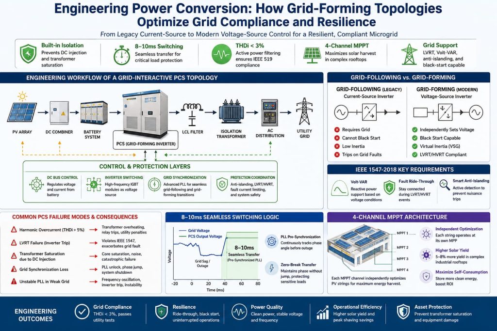
A modern grid-forming PCS is not merely a passive device; it is a comprehensive grid-interactive control system. To understand its value in microgrid stability, EPCs must break down its architecture into four functional layers:
- DC Bus Control Layer: Operates within the battery rack's allowed voltage and current window. Minimum and maximum battery voltage, BMS limits and the required charge/discharge power decide which PCS rating can deliver the duty.
- Inverter Switching Layer: Converts DC to AC through controlled power electronics. Grid-following and grid-forming describe the control behavior; the semiconductor type and an isolation transformer do not by themselves establish every operating mode.
- Grid Synchronization Layer: Aligns the converter with the AC reference when the configured mode requires it. Synchronization, islanding and reconnection must work together with site switching and protection.
- Protection Coordination Layer: Coordinates anti-islanding, permitted LVRT/HVRT behavior and converter current limits. Specify which events require ride-through and which require disconnection under the approved connection rules.
Engineering Workflow of a Grid-Interactive Power Conversion Topology
Map the full power path before buying the converter: battery, PCS, optional hybrid PV inverter, transformer, switchgear and site protection. The diagram below is a configuration example, not a claim that every PCS contains a four-channel MPPT stage or holds all the listed approvals.
Use the drawing to assign the interfaces and test boundary. For the offered MEGA PCS, check the battery DC window, isolation arrangement, BMS/EMS protocol and grid/off-grid control scope; validate the complete site power-quality and protection response before handover.
How IEEE 1547 Defines Interconnection Requirements
IEEE 1547-2018 fundamentally changed how EPCs must design distributed energy resources. The standard shifted from "do not harm the grid" to "actively support the grid." It defines interconnection requirements including ride-through and reactive power support, making PCS firmware as important as hardware design.
Volt-VAR and Reactive Power Support
Volt-VAR control changes reactive-power output within the converter's capability. Price both active power in kW and apparent power in kVA against the requested duty: reactive-power demand uses part of the available capacity. The required function and acceptance settings depend on the applicable IEEE 1547 and utility requirements, rather than a mandatory transformer topology.
Fault Ride-Through (LVRT and HVRT)
LVRT and HVRT behavior must match the applicable voltage/time profiles and connection settings. A voltage deviation or sag duration alone does not prove a failed test. Specify the operating category, protection coordination and measured response of the supplied firmware.
Smart Anti-Islanding
Anti-islanding protects the utility connection; an intentional island needs an approved separation and reconnection arrangement. Grid-forming capability does not remove anti-islanding duties. Agree the permitted modes and protection sequence so a nuisance trip or an unintended island does not become the EPC's commissioning problem.
Common PCS Failure Modes in EPC Projects
A rejected interconnection test costs another engineering visit and delays the equipment handover. Focus the RFQ and acceptance plan on the failure modes relevant to the site, then assign who corrects each issue. Neither transformerless nor isolated topology is a substitute for testing the configured system.
- Harmonic Performance: Check converter distortion and the complete installation at the agreed measurement point. Non-linear loads, operating power and the site network affect the result; THDi >5% is not a universal utility-rejection threshold.
- LVRT/HVRT Response: A trip is a failure only when the applicable ride-through profile required continued operation. Use the agreed event profile and configured protections rather than a universal 150 ms sag rule.
- DC Injection and Isolation: An isolation transformer offers galvanic separation. Confirm the permitted DC injection, transformer operating limits and protection response for the installation; transformerless topology alone does not prove excessive injection or equipment failure.
- Grid Synchronization Loss: A weak AC reference can challenge a grid-following control loop. Specify the expected voltage/frequency envelope and test the configured synchronization and protection response before site acceptance.
- Weak-Grid Control Interaction: Converter controls, network impedance and other sources can interact. Agree the required study, settings and witnessed operating cases with the EPC and utility so an instability problem is resolved within a defined scope.
Grid-Following vs. Grid-Forming: Why Topology Matters
The core architectural shift in modern microgrids is the transition from Grid-Following to Grid-Forming inverters to solve the failure modes mentioned above.
Grid-Following Inverters: Operation With an AC Reference
Grid-following inverters act as current sources. They rely on the utility grid to provide a stable voltage and frequency reference.
- Requires Grid: Cannot operate without an external AC voltage source.
- Cannot Black Start: If the grid drops completely, the inverter cannot restart independently.
- Low Inertia: Responds based on software loops, which can cause instability during rapid grid transients.
Grid-Forming Inverters (Modern Architecture)
A grid-forming control system establishes a voltage and frequency reference for the configured island. Virtual synchronous generator (VSG) is one possible control approach, not a function proved by an isolation transformer. Ask MegSolid to identify the offered MEGA PCS control mode, startup sequence and supported grid/island transitions before allocating black-start duties.
- Voltage Reference: A configured grid-forming system can establish the island's frequency and voltage. The battery operating window, inverter limits and connected load must support that operating case.
- Black Start: Specify this function separately, including the available SOC, auxiliary-power supply and connected load. An automatic on/off-grid switching listing alone does not establish restart of a de-energized plant.
- Virtual Inertia: Where included in the control package, this function shapes frequency response. Agree the settings and system-level test cases for the actual network and other connected sources.
Why Do C&I Energy Storage Systems Need a Built-in Isolation Transformer?
Transformerless PCS remains suitable for many applications. Choose built-in isolation where the project specification, utility interface or electrical separation makes it valuable, then coordinate the transformer, earthing and protection. The choice should remove an integration problem rather than add an unpriced external retrofit.
Galvanic Isolation and Safety
MegSolid integrates dedicated Power Conversion Systems (PCS) with Isolation Transformers directly on the production line. Select the offered configuration against the required AC rating, battery DC window, transformer and earthing arrangement, and operating modes. Ask MegSolid to identify the PCS model, firmware, interface map and which grid-support or islanded functions are included; verify these in the supplied datasheet and test scope.
- Galvanic Isolation: MegSolid's MEGA PCS range includes built-in isolation transformers. This provides electrical separation across the power path; verify the applicable DC-injection limit and installed protection arrangement instead of treating isolation as a blanket zero-injection approval.
- Transformer and Protection Coordination: Transformer impedance affects fault current, but the converter, protection settings and switchgear still need a coordinated design. For a larger equipment route, compare the actual rating and interface of Containerized ESS 5000INTL with the project's AC and battery requirements.
How Does a Harmonic Suppression System Maintain Grid Compliance?
Harmonic performance matters when the site includes drives, rectifiers and other non-linear loads. Use the applicable utility limits and agreed measurement conditions; avoid assuming every standard inverter produces 5% THDi or that one converter specification guarantees a compliant facility.
Harmonic Mitigation Engineering
The published MegSolid MEGA PCS series lists THDi <3%, six rated active-power options from 30 to 500 kW and built-in isolation. That is a useful equipment basis for the EPC. The quotation must also state whether the proposed converter includes any plant-level harmonic-compensation function and what the installed-system test will cover.
- Converter Performance: Separate the PCS's own harmonic specification from compensation of other loads on the site. A THDi listing does not by itself establish an active filter that cancels every industrial-load harmonic.
- IEEE 519 and PCC Acceptance: Agree the applicable limits, measurement location and operating cases with the utility or project authority. The published PCS THDi <3% is a component specification; the final site assessment must cover the configured installation.
How Does PCS Switching Protect Critical Industrial Loads?
A converter transfer-time label cannot protect a production line by itself. The actual interruption includes detection, converter response, switching equipment and the connected load. Give MegSolid the critical-load ride-through requirement and UPS/ATS arrangement so the engineering proposal can define the supported transfer mode and a witnessed acceptance test.
Synchronization, Switching Equipment and Load Ride-Through
- Synchronization Before Transfer: For a synchronized transition, verify the offered control sequence, voltage/frequency conditions and switching arrangement. PLL behavior and the resulting phase response depend on the configured system; there is no universal instant or jump-free transfer result.
- Transfer-Test Boundary: MegSolid's MEGA PCS page lists automatic on/off-grid switching without a universal 8–10 ms result. Require a model/firmware-specific test that records interruption, voltage response and the actual critical-load behavior. Keep UPS, ATS and generator duties explicit; a nonzero transfer interval is not a zero-break guarantee. Include the site safety scope alongside the BESS thermal runaway prevention guide.
Why Does the Hybrid Inverter Use 4-Channel MPPT for Solar+Storage?
Different roof orientations and shading patterns can justify separate MPPT channels. Match the array layout, string voltage and channel-current limits to the selected hybrid inverter. The benefit depends on the actual roof and string design, not the channel count alone.
Maximizing Solar Self-Consumption
For the Three-Phase Hybrid Inverter route, the published R50KH3 has four MPPT channels. Its PV inputs are a separate equipment scope from the MEGA isolated PCS; select and price the correct inverter for the roof layout and battery DC window.
- Independent Tracking: Four MPPT channels allow appropriately separated sub-arrays to track their own operating points within the inverter's input limits. This gives the designer more room to handle different roof planes and shading than one shared tracking channel.
- Solar Value: Compare the roof-specific yield calculation and inverter losses before promising a percentage gain. Four MPPT channels do not establish a universal 5–8% uplift. Match the PV inverter and hybrid solid-state battery configuration against the planned self-consumption and peak-shaving duty.
Common EPC Engineering Questions About PCS Compliance
Set the acceptance boundary before the converter ships. Assign battery DC compatibility, PCS grid support, transformer/protection coordination, PV inputs and critical-load continuity to named responsibilities so the EPC can close each issue without an open-ended integration bill.
Why PCS Fails Grid Approval and How to Pass Utility Interconnection Tests
Tie the factory checks to the final site tests: verify configuration and interfaces at FAT, then test the installed switching, metering and critical-load response at handover. Use the zero-export SAT test guide for the export-control part of the scope; it does not replace the transfer or utility-interconnection tests.
THDi Requirement for Industrial Inverters
For industrial inverters, distinguish the converter's THDi specification from the site PCC assessment. MegSolid publishes THDi <3% for the MEGA PCS series. IEEE 519 and the utility's applicable criteria must be assessed for the actual installation; they are not a universal requirement that every medium-voltage inverter show THDi below 3% at every operating point.
Illustrative Engineering Case: Medical-Device Manufacturing in San Diego, California
For a medical-device manufacturing project in San Diego, voltage sags and an unsupported islanding sequence can put controlled production at risk. Use this illustrative scope to connect the converter choice to the PLC ride-through requirement, local utility interface and the factory's recovery procedure.
For the 215kWh Outdoor Cabinet ESS route, a 500 kW target paired with five ESSA0100B-0215 cabinets gives 1,075.2 kWh nominal storage. Each cabinet is rated at 100 kW / 215.04 kWh. The available AC energy, parallel controls and common connection must be specified for the duty; a 1 MWh label is not the usable-energy result.
Engineering Scope and Witnessed SAT Checks
- Weak-Grid Conditions: Include the expected voltage/frequency envelope, load steps and other connected sources in the control review. Agree who supplies and approves the settings before the site team starts commissioning.
- Grid Compliance: For a San Diego connection, use the applicable SDG&E requirements and record the actual PCC power-quality result, operating power and protection settings. A 2.1% THDi claim needs its original measurement record; it is not a general MEGA PCS performance result.
- Critical-Load Transfer: Record the interruption and voltage response of the delivered configuration with the actual load. A reported 8.4 ms event would apply only to the tested setup; the published MEGA PCS page does not establish that result or a universal no-break capability.
Acceptance Outcomes to Require Before Handover
- Production Continuity: Demonstrate that the approved critical-load and UPS/ATS arrangement meets the defined ride-through and recovery requirement. Keep the pass criteria and remedial responsibilities in the handover record.
- Solar Integration: Verify the selected hybrid inverter's MPPT limits, battery compatibility and actual roof-specific production estimate. A four-channel design offers layout flexibility; the energy-yield result belongs to the project calculation.
- Grid Support: Witness the required LVRT/HVRT and reactive-power operating cases using the approved firmware and settings. The converter label alone does not establish utility acceptance.
- Commercial Boundary: This is an illustrative engineering scope, not a verified MegSolid San Diego commissioning record or a promise of production yield. Price the equipment, integration work, tests and recovery support as separate deliverables.
Engineering Comparison: Standard Grid-Following PCS vs. Grid-Forming PCS
EPCs must evaluate topological features when selecting power conversion equipment.
|
Engineering Feature |
Grid-Following Control |
Grid-Forming Control / Offered Configuration |
|---|---|---|
| Galvanic Isolation | Isolation arrangement is model-specific | MEGA PCS includes built-in isolation; verify earthing/protection |
| THDi Performance | Published converter specification and site test | MEGA PCS lists THDi <3%; assess the actual PCC separately |
| Switching Time | Configuration and switching-path dependent | Automatic on/off-grid switching listed; timing requires the delivered-system test |
| Black Start | Needs an external AC reference in grid-following mode | Specify black-start function, auxiliaries, SOC and load separately |
| Reactive Power (Volt-VAR) | Function/capability depends on the model and settings | Specify active/reactive limits and required utility test |
| Fault Ride-Through | Trip/ride-through must match the applicable profile | Verify LVRT/HVRT behavior for the offered firmware |
| Off-Grid Unbalanced Load | Phase capability is model-specific | Require the exact phase/current limits; do not transfer another inverter's 100% claim |
MegSolid Manufacturing Authority
MegSolid gives EPCs an equipment route from 30–500 kW isolated MEGA PCS to cabinet and container storage configurations. The published PCS options distinguish rated kW from maximum kVA and give model-specific battery voltage windows, plus BMS RS485/CAN and EMS RS485/TCP/IP interfaces. Bring the AC requirement, battery limits and site duties to our Huzhou engineering and manufacturing team: the OEM/ODM manufacturing quotation should identify the hardware, control scope and integration responsibilities before the order is placed.
References & Industry Standards
Use the standards below to define the applicable design and test scope for the offered equipment and installation. A reference to a standard is not a model certificate or a blanket claim that every listed function has been approved.
- IEEE 1547-2018: Standard for Interconnection and Interoperability of Distributed Energy Resources.
- IEEE 519: Recommended Practice and Requirements for Harmonic Control in Electric Power Systems.
- IEC 62933: Series of standards for electrical energy storage (EES) systems.
- UL 1741 SB: Standard for Inverters, Converters, Controllers and Interconnection System Equipment (Supplement B for grid support).
- IEC 62116: Test procedure of islanding prevention for utility-interconnected photovoltaic inverters.
- IEC 62477: Safety requirements for power electronic converter systems and equipment.
- IEC 62109-1/2: Safety of power converters for use in photovoltaic power systems.
FAQ
Q1: Why does a C&I energy storage system need a PCS with a built-in isolation transformer?
MegSolid's MEGA PCS includes built-in isolation, providing galvanic separation in a defined converter arrangement. Choose it where the site specification, utility interface or isolation requirement makes that useful, then coordinate earthing, fault protection and the applicable DC-injection limit. Isolation alone does not establish complete-system grid approval.
Q2: How does the inverter control system maintain THDi <3% for grid compliance?
The published MEGA PCS page lists THDi <3%. Check the supplied model's test conditions and distinguish its own distortion from any offered compensation of other site loads. IEEE 519 and the utility's PCC limits require an installation-specific assessment; the listing does not prove active harmonic filtering of the entire plant.
Q3: What is the difference between grid-following and grid-forming inverters?
Grid-following control uses an external AC voltage and frequency reference. Grid-forming control can establish that reference for a configured island. The offered firmware, battery limits, auxiliary supply and protection arrangement determine which functions are delivered; black start and virtual inertia must be specified rather than inferred from the transformer.
Q4: What are the common PCS failure modes in EPC projects?
Relevant failure modes include unacceptable harmonics at the agreed measurement point, incorrect ride-through settings, DC injection or transformer/protection mismatch, loss of synchronization and weak-grid control interaction. Set model-specific test cases and pass criteria; THDi >5% or a particular sag duration is not a universal rejection rule.
Q5: How does IEEE 1547-2018 influence PCS design?
Where applicable, IEEE 1547-2018 informs interconnection functions such as reactive-power behavior and ride-through. The supplied firmware, configured settings, utility requirements and accepted test evidence must match the project. The standard does not require every compliant converter to use an isolation transformer.
Q6: What is the switching time of the grid-forming architecture?
There is no universal 8–10 ms result for every grid-forming architecture. MegSolid's MEGA PCS page lists automatic on/off-grid switching without a numerical transfer-time guarantee. Specify the delivered firmware, switching equipment and load, then witness the interruption and voltage response. A UPS or other no-break duty must be defined separately.
Q7: Can the platform support 100% unbalanced loads in off-grid mode?
Only where the specific offered inverter or PCS and its per-phase limits support the duty. The R50KH3 hybrid-inverter page lists 100% unbalanced-load capability subject to its phase limits; that does not establish the same capability for every MEGA PCS. State each phase's load and the neutral/earthing arrangement in the RFQ.
Q8: Why do standard PCS fail grid approval, and how to pass utility interconnection tests?
A PCS can fail acceptance when the configured installation does not meet the applicable power-quality, protection, ride-through or interface requirements. Use the actual utility criteria and witnessed tests. Built-in isolation and the published MEGA PCS THDi <3% are useful equipment features, not automatic proof that the complete site will pass.
Q9: What is the THDi requirement for industrial inverters?
Use the applicable utility and IEEE 519 assessment for the installation and agreed PCC measurement conditions. MegSolid publishes THDi <3% as a MEGA PCS specification; this is not a universal medium-voltage rule that every inverter or whole facility must remain below 3% at every operating point.
Q10: Can MegSolid customize the firmware for specific local grid codes?
Request the supported control functions, firmware version, configurable settings and test scope in the project quotation. For German VDE-AR-N 4110 or California Rule 21 requirements, establish the applicable connection rules and model-specific evidence before promising approval. A general customization offer does not establish a certificate or accepted settings for every jurisdiction.
Q11: What is a grid-forming power conversion system (PCS)?
A grid-forming PCS uses control that can establish a voltage and frequency reference for a configured island. It needs the battery, converter, auxiliaries and site protections to support that duty. DC bus control, inverter switching, synchronization and protection remain part of the engineering scope; black start and virtual inertia are separately specified functions.
Q12: How fast must a microgrid inverter switch to prevent industrial equipment shutdown?
The required interruption limit comes from the actual critical load, process and UPS/ATS design. There is no universal 10–20 ms ride-through value for all PLCs or UPS systems. Test the complete delivered path, including switching equipment and load response; a measured nonzero interval must not be sold as zero-break power.
Q13: Why is THDi <3% important for commercial energy storage?
Lower converter current distortion can help the EPC manage power quality, but the measured result depends on the operating conditions and installation. MegSolid's published MEGA PCS THDi <3% gives a component specification to evaluate; assess the complete PCC against the applicable limits and other connected loads.
Get Your Custom Microgrid Engineering Consultation
For an isolated PCS configuration review, send MegSolid the SLD, AC voltage and earthing scheme, battery DC range and BMS limits, required grid-support or islanded modes, protection settings and communications requirements. The quotation should identify the supplied PCS/transformer arrangement, software configuration and evidence scope. Use the BESS factory acceptance test guide to define witnessed checks of the supplied configuration; site integration and utility acceptance remain project-specific.
Global Sales & HQ (Hong Kong):
FLAT 7, 11/F BLK C HANG WAI IND CTR, 6 KIN TAI ST, TUEN MUN, HONG KONG
- Email: [email protected]
- Phone: +852 59811073
R&D & Manufacturing Facility (Huzhou):
No. 898 Mengxi Road, South Taihu New Area, Huzhou City, Zhejiang Province, P.R.China
- Website: https://www.solidess.com/
