 Skip to content
Two quotations can both say 100 kW energy storage inverter while describing materially different supply packages. Review the included equipment, remaining integration work and final handover point before comparing price. Common formats include:
- A floor-standing bidirectional PCS with an isolation transformer inside the cabinet
- A 19-inch conversion module requiring an engineered enclosure, busbars, protection, cooling and system validation
- A three-phase hybrid inverter combining battery conversion with direct PV inputs
Rated kW or maximum efficiency alone can hide late transformer decisions, an unpriced cabinet, a battery voltage mismatch, duplicate PV conversion equipment or a commissioning dispute. The practical decision is: Where should the PCS supply boundary end for this project? MegSolid publishes three relevant formats in its energy storage inverter portfolio. Each format defines a different supply boundary and set of project responsibilities.
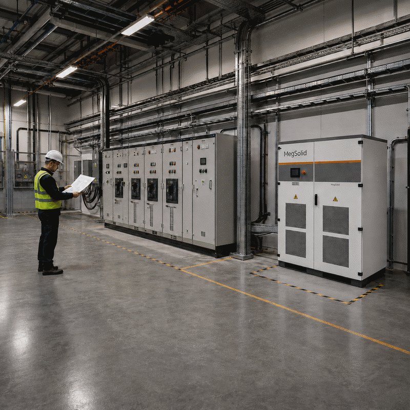
Let the Equipment Boundary Lead Product Selection
An EPC should identify the handover point on both sides of the converter before requesting a firm price. On the DC side, that means battery operating voltage, charge and discharge current, BMS protocol, disconnects and cable termination. On the AC side, it means voltage, neutral arrangement, isolation, switchgear, protection, metering and the point at which the site accepts the supplier's performance.
| Product format | What the product contributes | Work that remains project-specific | Reasonable starting fit |
|---|---|---|---|
| MEGA transformer-integrated PCS | Bidirectional PCS cabinet with built-in isolation transformer; 30–500 kW family | Battery package, site switchgear, protection settings, EMS logic, upstream transformer or MV interface where required | Battery-only C&I or microgrid projects that want the isolation transformer inside the PCS package |
| PMA rack-mounted modular PCS | 80, 105 or 125 kW conversion module in 19-inch 4U/5U form | Rack or cabinet, airflow, busbars, breakers, transformer decision, enclosure rating, system wiring and integration validation | OEMs and system integrators building a cabinet or container around a modular power block |
| R30KH3–R50KH3 hybrid inverter | Battery conversion plus direct PV inputs, four MPPT channels, three-phase grid and backup interface | PV string design, battery matching, backed-up-load boundary, protection, EMS and site connection | 30–50 kW commercial solar-plus-storage projects where PV input belongs in the same inverter duty |
This first screen is architectural. Detailed grid-forming, protection and control choices still require project engineering; MegSolid's PCS and inverter engineering guide explains the wider control questions. Apply a separate commercial comparison boundary to each supply package.
Choose MEGA When the Isolation Transformer Belongs Inside the PCS Package
The MegSolid MEGA power conversion system is the direct starting point when the project wants a floor-standing PCS with a built-in isolation transformer. The published family supports on-grid charging and discharging, off-grid operation, automatic on/off-grid switching and cold start. Its off-grid AC connection is 3W+N+PE at 400 V, and the cabinets use forced-air cooling.
| Model | Rated output | Maximum output | Published DC range | Maximum efficiency |
|---|---|---|---|---|
| MEGA0030TS | 30 kW | 33 kVA | 250–850 V | 96.3% |
| MEGA0050TS | 50 kW | 55 kVA | 320–850 V | 96.5% |
| MEGA0100TS | 100 kW | 110 kVA | 420–850 V | 97.1% |
| MEGA0150TS | 150 kW | 165 kVA | 420–850 V | 97.1% |
| MEGA0250TS | 250 kW | 275 kVA | 420–850 V | 97.3% |
| MEGA0500TS | 500 kW | 550 kVA | 500–850 V | 97.5% |
The built-in isolation transformer defines the internal supply boundary of the MEGA cabinet. MegSolid publishes model-specific internal transformer ratios from 100/400 V to 315/400 V. A medium-voltage point of connection can require an engineered step-up transformer and MV switchgear outside the MEGA cabinet. The SLD should identify the internal isolation function and the external voltage step-up function as separate equipment.
- Match the battery's minimum and maximum operating voltage to the selected MEGA model
- Confirm the maximum DC current and full-power operating window
- Freeze the 400 V site interface, neutral arrangement and earthing system
- Complete protection coordination and upstream switchgear studies
- Verify the cooling-air path and service clearances
- Place the published IP21 boundary inside a suitable room or container
- Show any external step-up transformer and MV switchgear on the approved SLD
Choose PMA When the Integrator Owns the Cabinet and System Assembly

The PMA modular energy storage PCS moves the supply boundary inward. The integrator receives a 19-inch conversion module and builds the balance of the power cabinet around it. This format suits repeatable cabinet platforms when the integrator owns electrical, thermal, mechanical and control integration.
| Model | Rated AC power | Maximum DC power | Module format | Published module weight |
|---|---|---|---|---|
| PMA080 | 80 kW | 96 kW | 19-inch 4U or 5U | 48 kg rear wiring / 50 kg front wiring |
| PMA0105 | 105 kW | 126 kW | 19-inch 4U or 5U | 48 kg rear wiring / 50 kg front wiring |
| PMA0125 | 125 kW | 150 kW | 19-inch 4U or 5U | 48 kg rear wiring / 50 kg front wiring |
Apply the PMA figures exclusively to PMA quotations and verify the selected connection arrangement. Key published interfaces include:
- 615–950 Vdc for the 3W+PE connection arrangement
- 650–950 Vdc for the 3W+N+PE connection arrangement
- 400 V on-grid rated voltage and 230/400 V off-grid output
- 98.7% published maximum efficiency
- Charge/discharge switching below 20 ms
- Support for 100% single-phase unbalance during off-grid operation
- IP20 power compartment and IP6X control compartment
- Define the final cabinet ingress-protection target
- Size inlet and exhaust paths, filters, sensors and fan control
- Verify busbar temperature rise, DC switching and AC switching
- Freeze internal cabling, service clearance and module-removal procedure
- Assign the transformer location and owner when galvanic isolation is required
- Normalize enclosure, protection, cooling, controls, testing and certification before comparing module and cabinet prices
- Request a controlled wiring diagram, communication register, parameter set, FAT sequence and exact PMA model designation
Choose the R Series When Direct PV Input Is Part of the Inverter Duty
The R30KH3–R50KH3 three-phase hybrid inverter occupies a separate product category because it combines direct PV input with battery and AC conversion duties. Each model has four MPPT channels, a 150–800 V battery range, a 380/400 V 3W+N+PE grid interface and a published backup switching time below 10 ms.
| Model | Rated AC output | Maximum charge/discharge power | Maximum PV input | Maximum AC output current |
|---|---|---|---|---|
| R30KH3 | 30 kW | 33 kW | 45 kW | 50.1 A |
| R40KH3 | 40 kW | 44 kW | 60 kW | 66.9 A |
| R50KH3 | 50 kW | 55 kW | 75 kW | 83.6 A |
This architecture suits a commercial site that wants PV generation, battery charging and three-phase backup managed through one inverter family. Battery-only container projects with external PV conversion call for a separate PCS boundary and architecture review.
- Confirm that direct PV input belongs inside the inverter duty
- Verify PV string voltage, current and MPPT allocation
- Match the 150–800 V battery range and BMS control behavior
- Define backed-up-load power and transition requirements
- Use the published IP65 enclosure, 530 × 280 × 850 mm dimensions and 73 kg mass for site planning
- Engineer the mounting structure, solar exposure, cable entry and local isolation
- Complete firefighting separation, protection and authority approval
Equal Rated kW Can Hide Different Project Scope
The MEGA0050TS and R50KH3 both publish 50 kW rated AC output, yet they answer different project questions. Architecture and supply-boundary screening belong ahead of rated-power comparison.
| Decision field | MEGA0050TS | R50KH3 | Procurement consequence |
|---|---|---|---|
| Primary format | Transformer-integrated battery PCS cabinet | Three-phase PV + battery hybrid inverter | Compare as different equipment scopes |
| Rated AC output | 50 kW | 50 kW | Equal kW can carry different project scope |
| Published battery range | 320–850 V | 150–800 V | Verify each battery range separately |
| PV input | Controlled MEGA data defines battery conversion duty | Up to 75 kW with four MPPT channels | Decide where PV conversion belongs |
| Isolation transformer | Built in | External project design defines the R-series isolation boundary | Allocate isolation and earthing responsibility explicitly |
| Mechanical form | Floor cabinet | 530 × 280 × 850 mm, 73 kg | Civil, access and installation work differ |
| Off-grid boundary | 400 V, 3W+N+PE; automatic switching | 380/400 V, 3W+N+PE; backup switch below 10 ms | Test the actual load and transition requirement |
The correct comparison starts with application and supply boundary, then moves to electrical capability. If the site has an existing 400 V switchboard, use the 400 V BESS connection guide to verify feeder current, fault duty, protection, neutral, earthing and metering after the initial PCS format has been selected.
Match the Complete DC and AC Interfaces Before Comparing Efficiency
Maximum efficiency becomes useful after the converter can operate across the battery's actual voltage window and deliver the required AC duty. Ask for the battery voltage at maximum and minimum SOC, beginning and end of life, and the applicable temperature limits. Use the full operating range as the matching basis; nominal voltage provides one reference point.
- Battery minimum, nominal and maximum voltage at the proposed series count
- Maximum continuous charge and discharge current permitted by the BMS
- PCS DC current limit and full-power voltage window for the exact model
- Grid voltage, frequency, three-wire or four-wire arrangement and earthing system
- Required active power in kW, apparent power in kVA and reactive-power duty
- Off-grid load balance, single-phase loads, nonlinear loads and motor-starting events
- Temperature, altitude, cooling-air condition and any model-specific derating
- Measurement boundary for efficiency and auxiliary consumption
The battery, PCS and controls must agree on permission and limits. The BMS and EMS communication architecture should identify who sends charge and discharge limits, which device owns the operating mode, what happens when a message is stale, and how the system records the event. Control compatibility requires verified register mapping, setpoint ownership and fault behavior.
Allocate Integration and Commissioning Ownership Before Award
C&I interface failures frequently occur across electrical, control and commercial handoffs. The order should name one owner for each deliverable and one acceptance record that proves completion. This is especially important for a PMA-based cabinet because more of the final product is created by the integrator. It also matters for MEGA and R-series projects whenever the battery, switchgear, EMS or PV equipment comes from another package.
| Interface | Decision to freeze | Evidence before shipment | Evidence at site |
|---|---|---|---|
| Battery to PCS | Voltage/current window, pre-charge, contactor sequence, BMS protocol | Approved compatibility matrix and wiring drawing | Charge/discharge test across agreed SOC window |
| PCS to EMS | Setpoint ownership, modes, ramp rates, alarms, stale-data behavior | Register map, parameter file and simulated I/O record | Dispatch, fail-safe and event-log test |
| PCS to AC system | Voltage, neutral, earthing, isolation, protection and metering | Approved SLD and protection concept | Phase sequence, trips, interlocks and power-quality record |
| Cooling and enclosure | Airflow, temperature limits, filters, service access and IP boundary | Thermal design and cabinet drawing | Temperature-rise and alarm verification |
| PV interface for R series | String voltage/current, MPPT allocation, isolation and curtailment | PV string schedule and inverter settings | MPPT, export-control and shutdown test |
| Operating transition | Grid-connected, backup or island sequence and permitted interruption | FAT scenario with acceptance limits | SAT waveform and timestamped event record |
Where the supplier and integrator are separate companies, the responsibility matrix should be contractually attached to the quotation. MegSolid's discussion of PCS and BMS integration failures is useful when defining these handoffs. For customers developing their own repeatable cabinet or container platform, the BESS OEM/ODM scope provides the broader manufacturing context.
Five Award Decisions That Create Avoidable Rework
- Awarding a PMA module as though it were a finished field cabinet, then discovering that enclosure, airflow, protection and certification were excluded.
- Treating the MEGA built-in isolation transformer as the site's medium-voltage step-up transformer without checking the published ratio and point of connection.
- Selecting an R-series hybrid inverter for its 50 kW label without confirming that direct PV input is actually part of the project architecture.
- Matching a battery and PCS by nominal voltage while ignoring the full SOC, temperature and ageing voltage window.
- Leaving BMS, EMS, protection and SAT ownership to be negotiated during commissioning.
Each mistake is preventable before a deposit is paid. Before award, the buyer should request an SLD, model-level interface table, inclusion schedule, test plan and named technical owner.

Put These Fields in a Decision-Ready PCS RFQ
| RFQ field | Information the buyer must provide | Supplier response required |
|---|---|---|
| Application | Peak shaving, backup, microgrid, PV self-consumption or another defined duty | Supported modes and control boundary |
| Power | Continuous kW, kVA, power factor, overload event and duration | Rated, maximum and time-limited capability for the exact model |
| Battery | Chemistry, series count, voltage window, current and BMS version | Compatibility matrix and DC operating limits |
| AC system | Voltage, frequency, neutral, earthing, transformer and fault level | Connection arrangement and required external equipment |
| PV | Existing or planned PV, string data and coupling requirement | Direct PV capability or clear exclusion |
| Mechanical | Location, dimensions, access and lifting constraints | Product dimensions, mass, clearances and service route |
| Environment | Temperature, altitude, humidity, dust and enclosure location | Operating limits, derating data and enclosure requirements |
| Controls | EMS/SCADA owner, protocols, meter locations and fail-safe states | Register map, interface responsibility and settings workflow |
| Documents | Required approval stages and language | Datasheet, drawings, BOM, manuals and certificate schedule |
| Testing | Witness points, FAT/SAT scenarios and acceptance limits | Method statement, instruments, data format and remedy for failure |
For a complete facility-level project, align this PCS package with the battery, EMS, thermal-management and protection decisions in MegSolid's C&I energy solution. A technically complete RFQ lets MegSolid answer with an exact model, an inclusion list and unresolved engineering items. It also lets the buyer compare competing offers on the same boundary.
Final Selection Recommendation
- Choose MEGA when the project calls for a separate battery PCS with the model-specific isolation transformer inside the PCS cabinet
- Choose PMA when a capable system integrator owns the rack, enclosure, protection, cooling and complete-system validation
- Choose R30KH3–R50KH3 when direct PV input and commercial three-phase backup belong to the same inverter duty
This architecture screen comes before final model approval. Final selection still requires the load duty, battery voltage/current envelope, AC system, protection, environment, controls and test criteria. MegSolid's portfolio provides distinct C&I product formats for different supply boundaries. The buyer can select the boundary that matches the project and then request evidence for the exact model.
FAQ
What is the main difference between a transformer-integrated PCS and a modular PCS?
A transformer-integrated PCS includes the specified isolation transformer inside the PCS package. A modular PCS is a power-conversion building block that still needs an engineered cabinet or rack, protection, cooling, busbars and any required transformer outside the module.
When should a C&I project evaluate the MegSolid MEGA PCS?
Evaluate MEGA when the project needs a separate battery PCS in the 30–500 kW published range and wants the model-specific isolation transformer integrated into the cabinet. Confirm the battery range, 400 V interface, environment and external site equipment before approval.
When is the PMA modular PCS the more suitable starting point?
PMA is a reasonable starting point when an OEM or system integrator is intentionally building a cabinet or container around an 80, 105 or 125 kW 19-inch PCS module and accepts responsibility for the remaining electrical, thermal and mechanical integration.
Why do the R50KH3 and a 50 kW MEGA PCS serve different projects?
Both publish 50 kW rated AC output, but the R50KH3 is a three-phase hybrid inverter with direct PV inputs and a 150–800 V battery range. The MEGA0050TS is a transformer-integrated battery PCS with a 320–850 V DC range. Their duties and supply boundaries differ.
Does the MEGA built-in transformer remove the need for a site transformer?
The MEGA transformer has a model-specific internal ratio and provides isolation within the PCS package. A project connecting to medium voltage may still need a separate step-up transformer and MV switchgear.
Is a PMA module a complete outdoor energy storage inverter cabinet?
PMA is published as a 19-inch 4U or 5U module. The integrator defines the final enclosure, IP rating, airflow, filters, busbars, breakers, cabling, access and system-level validation.
Why must the full battery voltage window be checked?
Battery voltage changes with SOC, temperature, series count and ageing. Full compatibility requires the minimum and maximum operating values to remain inside the exact PCS range while supporting the required current across the project duty.
Which PCS data should be fixed before comparing efficiency?
Fix the application, continuous kW, kVA, power factor, overload duty, battery voltage/current window, AC connection, operating mode, environment and measurement boundary. Maximum efficiency becomes meaningful only after those requirements are compatible.
Who should own BMS and EMS integration?
The contract should name one responsible party for register mapping, setpoint ownership, stale-message behavior, parameter files, FAT simulation, site commissioning and fault support. Complete compatibility evidence covers both the physical connector and the verified control behavior.
What should a buyer send for a model-level MegSolid PCS review?
Send the SLD, application, required kW/kVA, battery voltage and current window, BMS details, AC system, PV information, site conditions, protection concept, EMS/SCADA interface and FAT/SAT requirements.
Which energy storage inverter is used for a C&I battery-only retrofit?
A separate bidirectional battery PCS such as the MEGA family may be the initial direction when PV conversion remains outside the new package. The final choice depends on battery voltage, AC connection, isolation, protection and operating mode.
Which modular PCS can an energy storage cabinet OEM evaluate?
MegSolid publishes PMA080, PMA0105 and PMA0125 modules at 80, 105 and 125 kW rated AC power. An OEM must still engineer the cabinet, cooling, busbars, protection, transformer boundary and complete-system testing.
Which MegSolid inverter combines PV and battery inputs for commercial projects?
The R30KH3, R40KH3 and R50KH3 three-phase hybrid inverters combine a 150–800 V battery interface with four PV MPPT channels and 30, 40 or 50 kW rated AC output respectively.
How do I choose between MEGA, PMA and the R-series energy storage inverter?
Choose by project boundary: MEGA for a transformer-integrated battery PCS, PMA for an integrator-built modular cabinet, and the R series when direct PV input is part of the three-phase hybrid inverter duty. Verify the exact electrical and environmental requirements before award.
What is the DC voltage range of MegSolid C&I energy storage inverters?
It depends on the family and model. MEGA ranges run from 250–850 V up to 500–850 V; PMA publishes 615–950 Vdc for 3W+PE or 650–950 Vdc for 3W+N+PE; the R series publishes 150–800 V.
What must a C&I PCS quotation include?
It should state the exact model, rated and maximum power, battery window, AC interface, included transformer or enclosure, external equipment, communications, environmental limits, drawings, BOM, certifications, commissioning scope and FAT/SAT acceptance evidence.
