
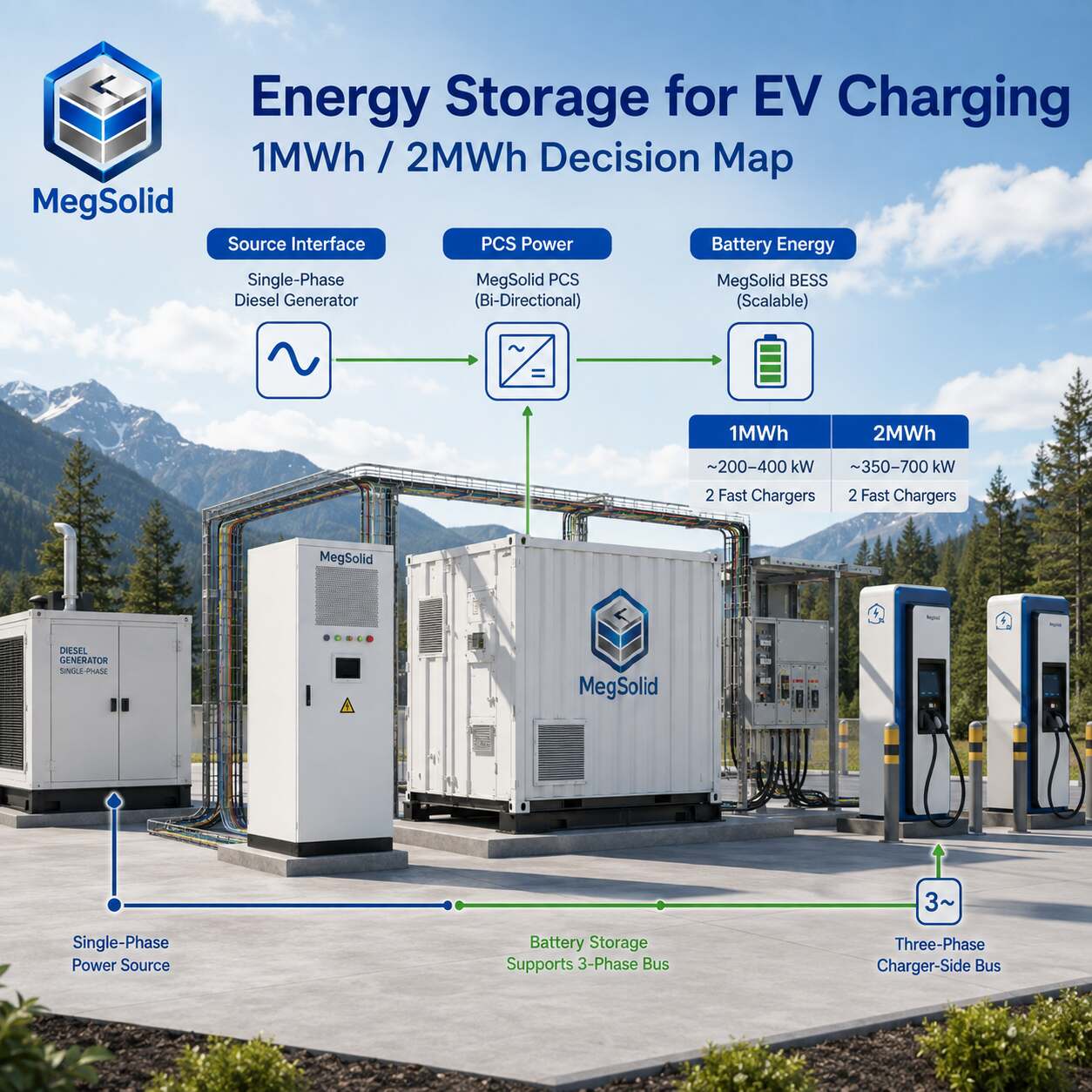
A commercial EV charging project in British Columbia can have a clear business case and still stall at the electrical interface. This customer’s requirement is specific: a diesel supply is available as a single-phase source, the charging equipment needs a three-phase supply, installation is planned indoors, and the early procurement comparison is between roughly 1,000kWh and 2,000kWh of battery storage.
MegSolid treats this as a system-integration decision. The battery, PCS, transformer or phase-conditioning interface, EV charger, generator, protection system and local approval package must all work from one controlled single-line diagram. The purpose of this solution is to help the project team turn that requirement into an engineering scope that can support a formal quotation and technical review.
Project position: off-grid commercial EV fast charging in British Columbia, with a diesel generator as the present energy source, a required three-phase charger-side bus and two preliminary BESS energy bands.
| Decision to make | Engineering evidence required | Why it changes the solution |
|---|---|---|
| Generator-to-BESS interface | Generator nameplate, voltage, frequency, phase arrangement, real kW, power factor, alternator details and operating limits | Defines the source-conditioning and protection design |
| Charger-side power | Charger model, AC input voltage, kW per connector, connector count and simultaneous-use rule | Defines required continuous and transient PCS power |
| Battery energy | Charging-session curve, daily vehicle count, energy per session, recharge windows and reserve target | Distinguishes a 1MWh-class system from a 2MWh-class system |
| Indoor installation | Room plan, clearances, ventilation, egress, fire strategy and structural loading | Determines whether the selected physical configuration can proceed |
| Canadian approval route | Authority having jurisdiction, electrical contractor, listed equipment scope and field-evaluation path where needed | Prevents an equipment list from reaching site before its approval route is defined |
Start With the Electrical Architecture
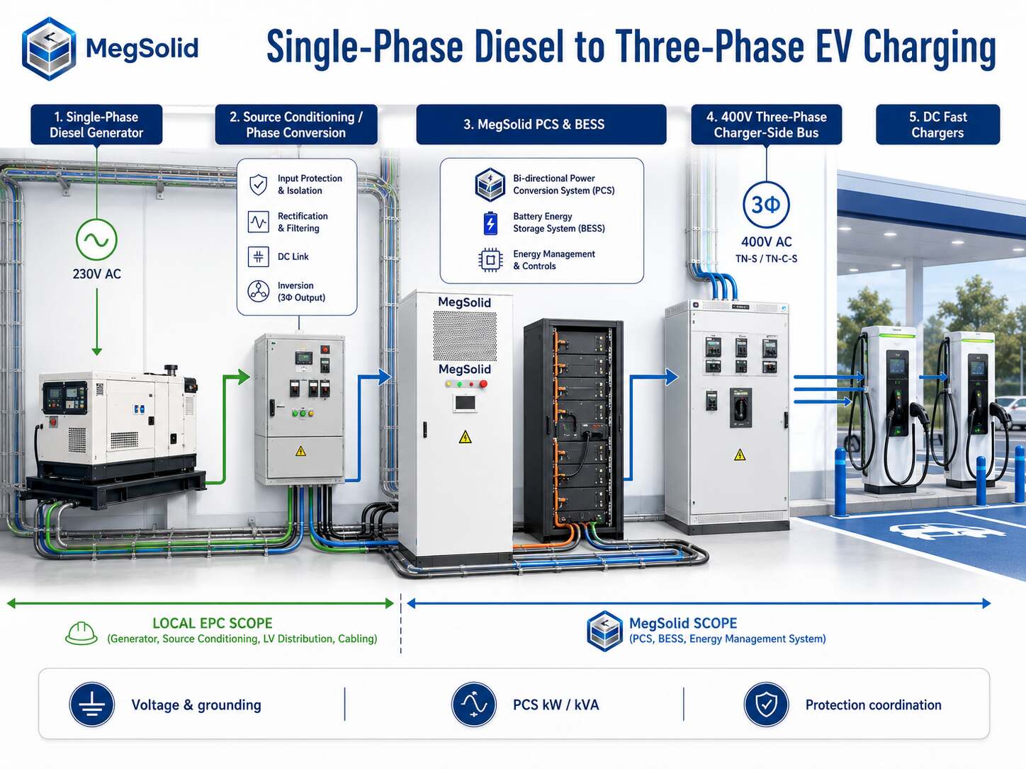
The project contains two separate conversion questions. They must be recorded independently.
- Source conditioning: the diesel generator’s single-phase output must be evaluated by the project electrical engineer against the required charger-side three-phase voltage, frequency, neutral arrangement, fault level and grounding method.
- Energy buffering: the BESS stores energy over time and delivers controlled power during charging events. Its PCS creates or supports the required AC bus only within the controlled system architecture and rating.
The approved single-line diagram should define the following sequence:
| System layer | Design responsibility | Information that must be fixed |
|---|---|---|
| Diesel generator | Generator supplier / local EPC | Single-phase source characteristics, fuel duty, governor behaviour, available real power and protection |
| Source-conditioning or phase-conversion stage | Project electrical engineer | Equipment topology, 400V three-phase bus design, isolation, grounding and fault coordination |
| BESS and PCS | BESS engineering package | DC energy, PCS kW/kVA, operating modes, BMS/EMS signals and protection interface |
| Charger-side distribution | EPC / charger supplier | Charger AC input requirement, distribution board, breakers, meter locations and cable routes |
| DC fast chargers | Charger supplier | Charger power, connector standard, power sharing, control protocols and vehicle-service target |
Verified PCS integration points:
- Power class: MEGA TS is a 30–500kW energy-storage PCS range, with model steps through MEGA0500TS.
- AC side: 400V, 3W+N+PE and a built-in isolation transformer in the controlled reference.
- Controls: automatic grid/off-grid switching; BMS communication by RS485/CAN; EMS communication by RS485/TCP-IP.
- System role: supports the BESS side after source conditioning, voltage and protection philosophy are approved.
Review the relevant energy storage inverter and PCS range when defining the power-conversion package.
Project interfaces that the local EPC must lock:
- A dedicated, project-engineered single-phase-to-three-phase conversion stage.
- The charger-side transformer or conversion interface when the charger requires a voltage other than 400V.
- Grounding, fault coordination and protection boundaries across the generator, conversion stage, PCS and charger bus.
Separate Charger Power From Battery Energy
The 1MWh versus 2MWh comparison becomes useful only after the team separates power from energy.
| Item | Unit | What it answers |
|---|---|---|
| Charger output demand | kW | How much power vehicles request at a given time |
| Generator available real power | kW | How much of that demand the generator can carry continuously at the approved duty point |
| BESS discharge power | kW or kVA | How much of the charging event the PCS and battery system must support |
| Battery energy | kWh or MWh | How long the system can sustain the required discharge pattern before recharge |
| Recharge window | hours | Whether the generator can restore the required state of charge between charging events |
Use the design-day interval record alongside daily energy totals. The working calculation is:
Required BESS discharge power for each interval = simultaneous EV charging demand − approved generator contribution.
Preliminary battery energy = the sum of BESS-supplied energy across the design-day intervals + the project reserve + the engineering allowance for the approved operating window.
Use these inputs in every 15-minute interval:
- Approved generator real power at the actual temperature, altitude, fuel duty and maintenance condition.
- Charger operator’s real power-sharing logic, including whether connectors can run at full output together.
- Battery reserve target and generator recharge time between charging events.
Decision rule:
- Brief high-power events mainly determine PCS kW.
- Repeated charging events determine battery MWh and recharge capability.
- The upstream source must sustain design-day average charging energy so the battery can replenish during lower-load periods, as illustrated in the battery-buffered charging case study.
For a wider explanation of charger power, available supply and BESS dispatch, see MegSolid’s existing EV fast-charging station BESS article. This BC project remains distinct because the critical design point is the single-phase diesel source feeding a three-phase charging system.
1MWh and 2MWh Energy-Class References Before Indoor Layout Approval
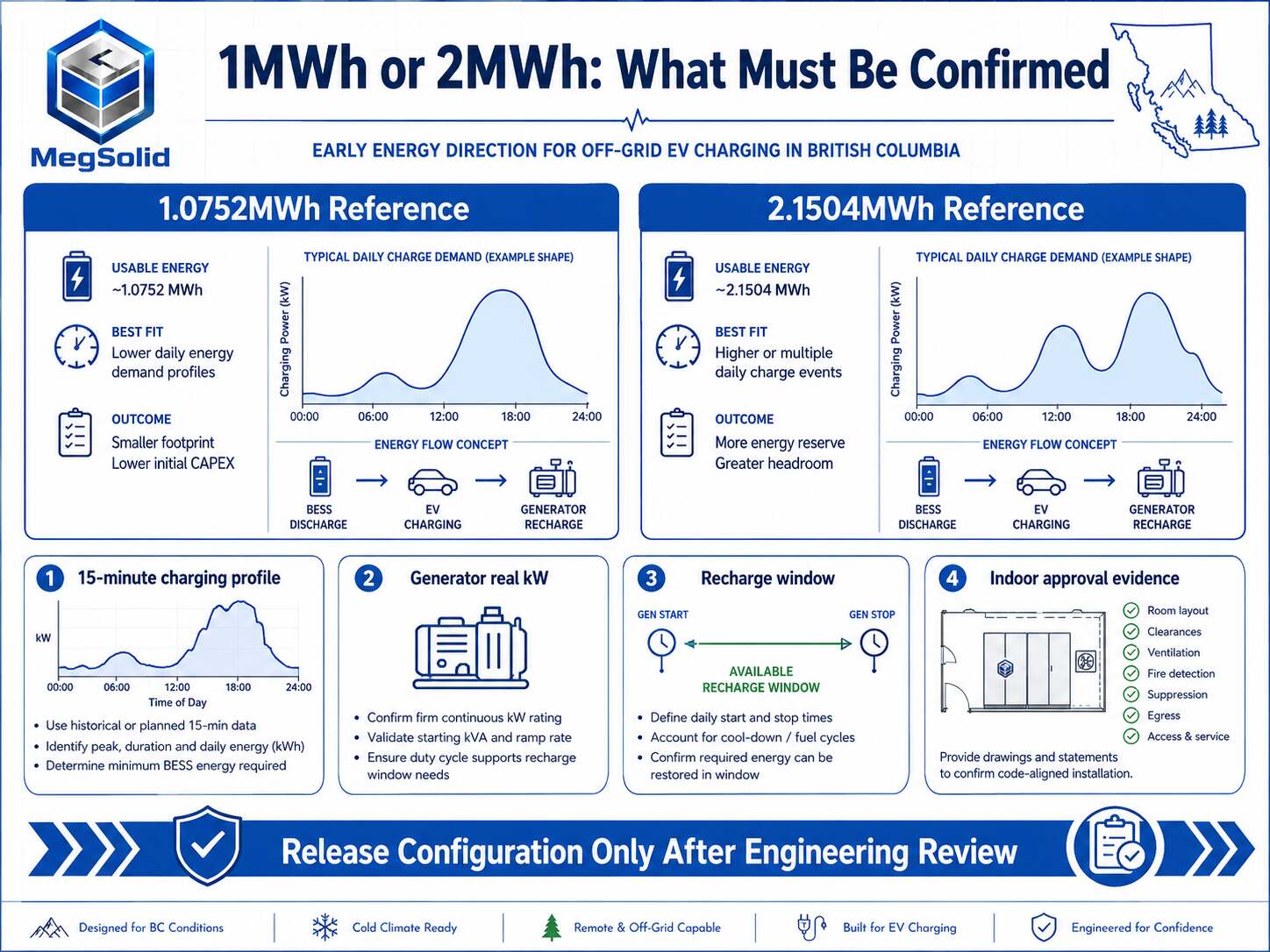
The customer requested two energy bands. MegSolid’s current public containerized C&I reference provides two relevant electrical starting points. These are energy-class references for the early comparison. Final configuration depends on the controlled load profile, the approved indoor siting design and current model documentation.
| Preliminary direction | Verified public data | What the project team still needs to confirm |
|---|---|---|
| ESSC0500B-1075 energy-class reference | 500kW rated AC power; 1.0752MWh rated energy; 3.2V/280Ah LFP cells; 400V AC; 3W+N+PE; 6,058 × 2,438 × 2,896mm; 21,000kg | Charger duty curve, dispatch kW, recharge interval, indoor room feasibility and certificate scope |
| ESSC1000B-2150 energy-class reference | 1,000kW rated AC power; 2.1504MWh rated energy; 3.2V/280Ah LFP cells; 400V AC; 3W+N+PE; 12,192 × 2,438 × 2,896mm; 38,000kg | Charger duty curve, dispatch kW, recharge interval, indoor room feasibility and certificate scope |
Shared verified reference points:
- LFP cells and intelligent temperature-controlled air cooling.
- Listed isolation-transformer ratio: 315/400.
- Listed off-grid voltage distortion: up to 1% with a linear load; up to 5% with a nonlinear load.
Use the 1.0752MWh direction when:
- The design-day BESS energy remains inside its controlled operating window.
- The calculated dispatch duty aligns with the 500kW AC power class.
Move the review to the 2.1504MWh direction when:
- Repeated charging energy is larger.
- The calculated power requirement is larger.
- The recharge window requires more stored energy to maintain the charging-service pattern.
Before treating either reference as final, submit the 15-minute charging record and confirm acceptance tests, usable energy, charger compatibility and Canadian approval evidence.
For deployments that require a different physical form factor, containerized ESS deployment should be reviewed before the room and logistics design are released. The container references provide dimensions and mass for preliminary energy comparison; their public data leaves indoor-installation classification unresolved. Indoor siting therefore requires a separate building, fire, egress, ventilation, structural and approval review before a product configuration is released.
Build the Generator and PCS Scope Before Comparing Batteries
An early BESS comparison often reaches a battery capacity decision before the project has frozen the source and charger interfaces. The following decision matrix keeps procurement in the right order.
| If the engineering data shows… | The solution review should focus on… | Procurement output |
|---|---|---|
| Short, high-power charging peaks with recovery intervals | PCS dispatch kW, generator load acceptance and battery recharge rate | PCS class, source-conditioning interface and dispatch logic |
| Repeated charging events through the day | Total BESS energy, generator runtime, reserve and recharge window | 1MWh-class or 2MWh-class energy direction |
| Chargers requiring a different AC voltage than the BESS bus | Charger-side transformer or distribution interface | Voltage schedule, transformer responsibility and protection coordination |
| Multiple chargers with power-sharing software | Charger communications and EMS dispatch priority | Communication matrix and operating-state table |
| A generator source with limited real kW | Phase-conversion design, source capacity and generator duty | Generator validation report before final BESS release |
PCS selection checkpoints:
- Verified MEGA TS steps: 30, 50, 100, 150, 250 and 500kW.
- External-PCS projects can use those steps for an initial power-class review.
- The controlled reference lists up to four units in parallel.
- Parallel topology, available fault current and field wiring require the approved project design.
The related power conversion architecture page gives more background for the PCS discussion.
Define Indoor Installation and BC Approval Evidence Early
BC approval checkpoints:
- Electrical equipment installed under the BC Electrical Code must be approved under Rule 2-024.
- Field-assembled energy-management equipment needs an overall approval or a documented variance and field-evaluation route.
- The Registered Professional reviews design, performance values, commissioning and maintenance requirements where applicable.
- EV charger installation permits are legally required in BC.
Use the Technical Safety BC EVSE/EVEMS bulletin and BC EV charger permit information to define the local pathway.
Before a purchase document is issued:
- Match certificates to the exact MegSolid model and system boundary presented for review.
- Confirm Canadian approval evidence or a field-evaluation path with the inspection authority, electrical contractor and engineer of record.
- Include the BESS, PCS, charger and assembled control system in the approval matrix.
For an indoor 1MWh or 2MWh project, complete these records before issuing purchase documentation:
| Record | Project question it resolves |
|---|---|
| Approved single-line diagram | Where source conditioning, PCS, BESS, charger distribution and protection sit |
| Load and charging profile | Whether power and MWh values support the intended charging service |
| Generator validation sheet | Whether real generator output and operating duty support recharge and charging events |
| Equipment approval matrix | Which model, assembly and system boundary each certificate covers |
| Indoor general arrangement | Room access, lifting route, equipment mass, clearance, ventilation, fire strategy and egress |
| EMS operating-state table | Priority between charging service, battery reserve, generator loading and planned maintenance |
| Commissioning and acceptance plan | Functional tests, alarms, interlocks, communications, charger power-sharing and handover criteria |
This documentation-first approach aligns with the engineering review framework used by EPC teams. It gives the local approval and installation parties the evidence required to assess a complete project package.
Supply Boundaries for This EV Charging Solution
The customer’s question includes PCS and transformer pricing. The cleanest approach is to issue the quote in named packages, each tied to the approved single-line diagram.
| Package | Typical items to define | Responsible technical confirmation |
|---|---|---|
| BESS package | Battery energy system, BMS, thermal management, enclosure, configured PCS where included, EMS interfaces and factory documentation | MegSolid engineering and approved datasheet |
| PCS package | PCS model, AC bus voltage, kW/kVA, isolation-transformer configuration, controls and communication ports | MegSolid engineering plus project electrical engineer |
| Source-conditioning package | Single-phase generator interface, phase-conversion or conditioning equipment, generator protection and generator-control integration | Local EPC, generator supplier and electrical engineer |
| Charger package | DC chargers, connectors, charging-management platform, charger AC input gear and charger-side commissioning | Charger supplier and local EPC |
| Site package | Building works, room design, cable routes, switchgear, grounding, permits, inspection coordination and installation | Local EPC and authority-facing team |
MegSolid technical input can cover:
- BESS product-direction data.
- PCS interface data.
- A preliminary 1MWh/2MWh comparison scope based on the submitted project record.
Evaluate the full C&I Energy Storage system range alongside the exact source-conditioning and charger packages. Rated energy is one item in the full system scope.
PV boundary: PV equipment is outside MegSolid’s current supply scope. A later PV package should be procured locally and added to the EMS operating-state table through site-specific engineering.
The Information Needed for an Engineering Solution
Send the following data as one package to turn the 1MWh/2MWh comparison into a controlled technical proposal:
- Generator datasheet, nameplate image, single-phase voltage and frequency, rated and continuous real power, control mode and fuel-duty limits.
- Charger datasheets showing AC input, total charging power, connector count, power sharing and required three-phase voltage.
- A 15-minute design-day charging schedule, including the number of vehicles, expected energy per session and simultaneous charging events.
- Indoor room drawing with ceiling height, access doors, lifting route, floor loading, ventilation route, fire provisions and required clearance zones.
- Required Canadian approval route, local authority contact, electrical contractor details and target commissioning date.
- A clear statement of whether the charger needs continuous service through generator maintenance or only during defined operating periods.
Send the generator datasheet, charger AC-input data and 15-minute charging schedule to [email protected]. MegSolid can return a preliminary BESS/PCS interface checklist, a 1MWh/2MWh comparison scope and the data still required before configuration release.
Send the room layout, local approval requirement and target three-phase bus voltage to [email protected]. The response can identify the product documentation, equipment boundaries and technical questions needed for the local EPC and approval team.
MegSolid supports the BESS and PCS side of this decision with controlled product data and project-specific engineering inputs. For a complete product and integration conversation, use project engineering package support after assembling the records above.
FAQ
What should the generator supplier provide before BESS sizing begins?
The generator supplier should provide the nameplate, voltage, frequency, phase arrangement, rated and continuous real kW, power factor, alternator data, load-acceptance information, control mode and operating limitations. These figures establish the source side of the single-line diagram and the recharge window.
Can a 1MWh BESS be selected from charger power alone?
Charger power establishes the PCS and battery discharge-power question. Battery energy requires the charging-event duration, event frequency, recharge periods and operating reserve. A 15-minute design-day record gives the correct basis for the comparison.
What makes a 2MWh BESS relevant for EV charging?
A 2MWh-class direction becomes relevant when repeated charging events, longer energy-support periods, a larger operating reserve or a limited recharge window push the calculated energy requirement beyond the 1MWh-class operating window.
Why does a single-phase diesel source require a separate engineering check?
The EV chargers and the 400V BESS/PCS bus operate within a three-phase architecture. The generator interface must define phase conditioning, voltage, grounding, protection and generator control before equipment responsibilities can be released.
Which MegSolid PCS range is relevant to a commercial fast-charging project?
The controlled public reference lists MEGA0030TS through MEGA0500TS at 30–500kW, with 400V three-phase AC connection and built-in isolation transformer. Final selection depends on calculated BESS dispatch power and the approved single-line diagram.
What is the verified public data for the 1MWh-class energy reference?
ESSC0500B-1075 is listed at 500kW rated AC power and 1.0752MWh rated energy, using 3.2V/280Ah LFP cells. Its listed dimensions are 6,058 × 2,438 × 2,896mm and listed weight is 21,000kg.
What is the verified public data for the 2MWh-class energy reference?
ESSC1000B-2150 is listed at 1,000kW rated AC power and 2.1504MWh rated energy, using 3.2V/280Ah LFP cells. Its listed dimensions are 12,192 × 2,438 × 2,896mm and listed weight is 38,000kg.
How should the BESS, PCS and transformer quote be divided?
The quotation should name the BESS package, PCS package, generator source-conditioning package, charger package and site installation package separately. Each line should reference the approved single-line diagram and list the party responsible for engineering confirmation.
What approval information is needed for an indoor BC project?
Start with the applicable authority, electrical contractor, equipment approval matrix, Canadian marks or field-evaluation route, room layout, fire strategy, egress plan and commissioning scope. Technical Safety BC must be consulted for the current local pathway.
What information is required for a preliminary engineering proposal?
Submit generator data, charger data, 15-minute charging profile, indoor room drawing, required approvals, local EPC contact and target commissioning date. This allows MegSolid to define BESS and PCS interfaces without assigning unsupported runtime or approval claims.
What does energy storage for EV charging mean in British Columbia?
For a commercial BC charging site, energy storage for EV charging is a BESS and PCS arrangement that stores energy and dispatches it to support the charger-side AC bus according to an approved operating plan. The local electrical and approval pathway determines the final installed system boundary.
Can a diesel generator support off-grid EV fast charging in Canada?
It can form part of an off-grid charging solution when the generator’s real kW, phase arrangement, source-conditioning equipment, charging profile and recharge window are engineered together. The generator supplier and electrical engineer validate the final interface.
What is a battery buffered EV charger for a Canadian commercial project?
A battery buffered EV charger uses a BESS to provide controlled power during high-demand charging intervals while the upstream source supplies energy across the operating window. It requires a defined charging profile, EMS dispatch plan and local approval review.
How do I choose between a 1MWh and 2MWh BESS for EV charging?
Choose the preliminary energy band from the 15-minute design-day charging profile, the approved generator contribution, the recharge window and required operating reserve. Charger kW establishes the PCS power question; repeated energy demand establishes the MWh question.
What must be confirmed for a single-phase diesel generator feeding three-phase EV charging?
The project electrical engineer must confirm the source-conditioning or phase-conversion topology, bus voltage, grounding, protection coordination, generator control and charger input requirements on the approved single-line diagram.
Which project documents should be sent for a BESS and PCS solution review?
Send the generator datasheet, charger datasheets, 15-minute charging schedule, indoor layout, required Canadian approval route and target commissioning date. These inputs support a preliminary BESS/PCS interface scope and product-direction review.