 Skip to content
A commercial and industrial battery project is ready for procurement only when the design states what the system must power, for how long, at which voltage and power factor, and how it will behave at the point of common coupling. MegSolid uses those inputs to screen the battery, PCS and controls, while the local EPC completes the site-specific 400 V switchboard connection, outdoor BESS foundation design and SCADA point list.
A weak design usually shows up when one of six outputs is missing: required continuous kW, required kVA, required AC kWh, the PCC operating limit, the site environmental envelope and the acceptance tests. If one of these is missing, a product can look correct on a quotation and still fail the load, trip the switchboard, recharge into a second demand peak or arrive without the evidence needed for handover.

The Design Must Produce Six Verifiable Outputs
Battery energy storage system design starts with measured site conditions and ends with values that can be checked during FAT and SAT. A useful design basis should identify:
- 1. Continuous and transient AC power: the sustained site deficit, motor-starting duty, overload duration and reactive-power requirement.
- 2. Required AC energy: the protected-load or peak-shaving energy at the agreed delivery point, including the operating SOC window and end-of-life requirement.
- 3. Electrical interface: PCC location, nominal voltage, frequency, fault level, breaker arrangement, cable route, earthing method and protection philosophy.
- 4. Control behavior: operating modes, priorities, CT and meter locations, setpoints, alarms, communications and fail-safe state.
- 5. Environmental boundary: temperature, altitude, humidity, condensation risk, dust, water, salt exposure, solar load, acoustic receptor and maintenance access.
- 6. Acceptance evidence: calculations, drawings, datasheets, protection settings, FAT records, SAT procedures, capacity-test boundary and handover documents.
These outputs separate a product-family screen from an issued-for-construction design. A screen can pick a family. Cable sizes, protection settings, civil details and permits still need site data and the local engineer.
Start With the Load Profile and Then Review Battery Nameplate Ratings
Do not start with a battery catalogue. Start with meter data, the loads that must stay online and the event the BESS has to carry.
For peak shaving, use interval data at the same meter that defines the utility demand. A 15-minute billing interval can hide short production peaks, so faster data is useful for checking PCS response and overload duty. For backup, list the loads in stages rather than entering one total kW value. Define which controls, emergency lights and communication systems require uninterrupted supply; schedule pumps, compressors or production equipment for later stages; keep approved deferrable loads off.
A practical input pack contains:
- at least one representative month of interval demand data, plus known seasonal or production changes;
- a protected-load schedule with kW, kVA or power factor, start method and required duration;
- the single-line diagram and the proposed PCC;
- transformer rating, impedance, voltage and available fault-current information;
- generator rating, ATS sequence, minimum loading and reverse-power restrictions;
- PV inverter ratings, export limits and measured or modelled production;
- ambient temperature, equipment-intake temperature, altitude, humidity and exposure conditions;
- the required recovery time before the next shift or next expected outage.
If measured data is incomplete, write the assumption and the evidence still required. “80 kW protected load for 60 minutes, subject to one-week logging and compressor-start capture” can start a screen. “About 100 kW backup” cannot.
Separate Power, Apparent Power and Energy
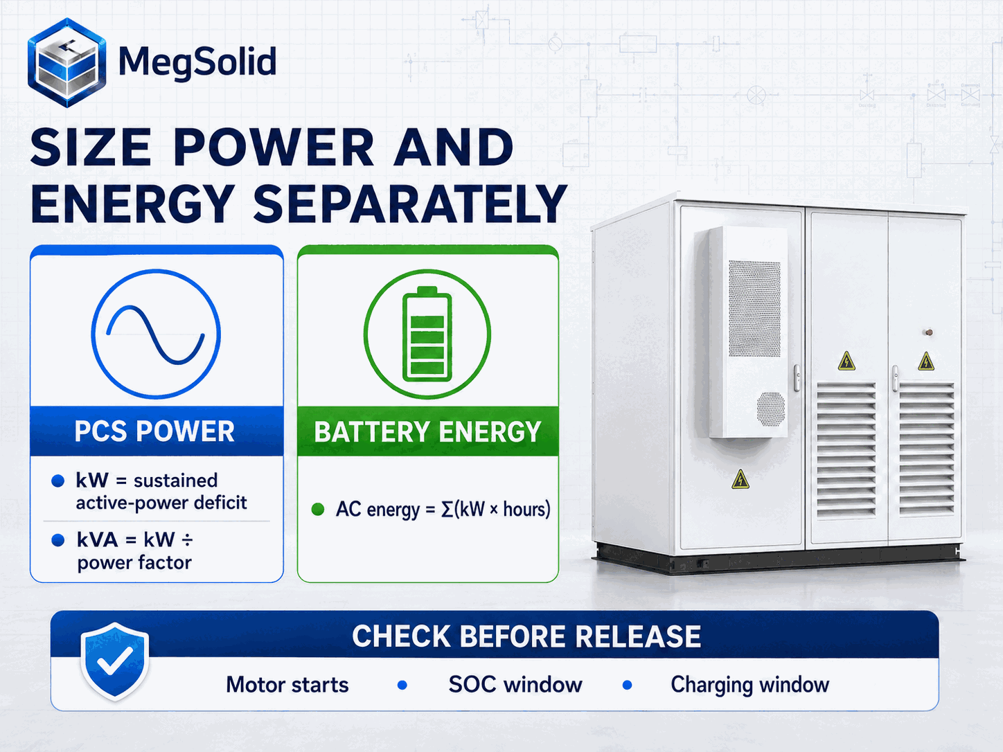
kW, kVA and kWh answer different design questions. kW describes active power. kVA sets the current-carrying requirement of the PCS and AC equipment. kWh describes how long the battery can support a defined load after losses and operating limits are applied.
For a sustained site deficit:
Required continuous AC power ≥ highest sustained site deficit after approved load shedding
Where the load power factor is below unity:
Required apparent power (kVA) ≥ required active power (kW) ÷ design power factor
For staged backup duty:
Protected-load AC energy = Σ(load kW × stage duration h)
When the calculation begins with nominal battery energy:
Required nominal battery energy ≥ protected-load AC energy ÷ (usable SOC fraction × AC delivery efficiency × end-of-life capacity fraction)
Every factor needs a defined boundary. AC delivery efficiency must be appropriate to the operating power, temperature and conversion path. The usable SOC fraction must match the operating strategy, including any reserve held back for battery protection. The end-of-life factor must match the capacity that the contract requires at the stated service point.
If a supplier provides warranted usable AC energy, compare it with the load requirement at the same AC boundary. Do not divide that warranted AC value by PCS efficiency again. Use “maximum system efficiency” as round-trip efficiency only when the datasheet and test method explicitly define it that way.
Transient duty is a separate check. A PCS that carries 80 kW continuously still needs a separate check for an 80 kW compressor start. The starting current, starting method, voltage-dip limit, PCS overload curve and simultaneous-load sequence require confirmation before the cabinet can be locked.
Decide What the BESS Must Control
One C&I BESS can serve several objectives, but those objectives need an explicit priority order. Otherwise, two individually reasonable setpoints can compete for the same battery capacity.
Peak shaving
The controller measures import at the PCC and discharges before the averaged utility demand crosses the target. The design needs the billing interval, meter latency, PCS response, discharge ceiling, SOC floor and a recovery rule that does not create another peak. The PCC control specification should define CT polarity, data quality, communication loss and the response to stale measurements.
Backup power
The design reserves enough power and energy for the staged critical-load profile. It also defines transfer behavior, grid-forming or grid-following responsibility, black-start conditions, neutral and earthing arrangements, and the order in which loads return. A product page without a model-specific transfer time does not prove seamless transfer.
PV charging and self-consumption
The EMS charges the battery when PV exceeds the permitted site use or export level, subject to battery voltage, SOC, temperature and PCS limits. PV modules, array construction and local solar installation normally remain in the local EPC or procurement scope unless the contract says otherwise. The BESS design still needs PV power data because charging availability affects the recovery plan.
Generator coordination
The control sequence must prevent unwanted reverse power, unstable low loading and competing voltage or frequency controls. Generator minimum loading, ramp capability, start delay and breaker status should be known before final logic is released. The design should follow a defined BESS and diesel-generator control sequence, not a generic “generator compatible” note.
Zero export
Zero export is closed-loop control at the PCC. A datasheet checkbox does not define the loop. The meter direction, fail-safe import bias, export threshold, delay, control deadband and loss-of-communications response all belong in the functional description.
Define the PCC, Switchboard and Protection Boundary
The point of common coupling is the reference point for import, export, protection and control. Moving the CT from the utility incomer to a downstream board changes what the EMS sees. A BESS can regulate the wrong boundary perfectly if the design does not identify the PCC on the single-line diagram.
The electrical design should record:
- switchboard bus rating, short-circuit withstand and spare-way arrangement;
- transformer rating, impedance, vector group and neutral treatment;
- PCS nominal voltage and the need for an isolation or step-up transformer;
- cable conductor, insulation, installation method, grouping, route length and ambient correction;
- breaker making and breaking capacity, discrimination and remote-trip requirements;
- overcurrent, earth-fault, voltage, frequency, anti-islanding and interconnection functions;
- CT ratio, class, burden, polarity, location and meter communication path;
- emergency stop, fire-system interface and the safe state following auxiliary-power loss.
The PCS rating does not prove the existing switchboard can take the connection. Fault-current contribution, thermal capacity, protection coordination and local interconnection rules require project-level studies. IEEE 1547-2018 covers DER interconnection and interoperability with electric power systems, while IEEE 1547.9-2022 provides guidance for applying those requirements to energy storage. Local grid codes and the authority having jurisdiction remain controlling.
Screen the Product Architecture Against the Site
Product selection should follow the required boundary values, not the nearest nominal kWh figure. The table below is a preliminary MegSolid product-family screen based on currently published data. Final selection requires a controlled datasheet, project temperature and altitude, duty cycle, power factor, protection study and approved electrical architecture.
| Product family | Published power and energy | AC interface | Thermal and site notes | Preliminary fit |
|---|---|---|---|---|
| ESSA0100B-0215 | 100 kW / 215.04 kWh | 400 V, 50/60 Hz | Intelligent air cooling; IP54; published operating range 0–45°C | Compact C&I cabinet where the power, energy and environment remain inside the controlled limits |
| Energon 261.24 | 125 kVA / 261.24 kWh | 400 V or 480 V, 50/60 Hz | Liquid cooling; published operating range −20–55°C; derating above 45°C and above 2,000 m | Sites needing a liquid-cooled architecture or wider ambient range, subject to kW at the project power factor |
| ESSC1000B-2150 | 1,000 kW / 2.1504 MWh | 400 V | Intelligent temperature-controlled air cooling | Larger C&I or industrial duty where a megawatt-class integrated system suits the site architecture |
| 5000INTL | 2.7 MW / 5.0159 MWh | 690 V | Smart liquid cooling; IP55; published operating range −30–55°C | Multi-megawatt projects with a 690 V internal architecture and project-specific MV connection design |
Do not rewrite Energon’s 125 kVA as 125 kW until power factor and the controlled datasheet are checked. A 5.0159 MWh container also leaves a 3 MW deficit uncovered if the PCS is 2.7 MW. Extra energy extends duration. It does not raise PCS power.
ESSA models currently list LFP cells. The ESSA platform can support project-specific cell configurations, but the family name alone does not prove that every supplied unit uses solid-state cells. Chemistry, cell supplier and compliance evidence must match the quoted model and project documentation.
Worked Factory Example: From Meter Data to a Design Band
Consider a factory with a 500 kW permitted import limit. Fifteen-minute meter data shows a 420 kW normal demand and a recurring 560 kW production peak. The preliminary peak-shaving deficit is:
Peak-shaving power = 560 kW − 500 kW = 60 kW
This establishes the minimum active-power contribution during the measured peak. The final PCS requirement also includes control margin, reactive-power duty, data latency and any faster peaks found in higher-resolution logging.
The same factory has a two-stage protected-load schedule:
| Stage | Load | Duration | AC energy |
|---|---|---|---|
| Controls, communications and essential drives | 80 kW | 15 min | 20 kWh |
| Reduced essential process load | 45 kW | 45 min | 33.75 kWh |
| Total | 60 min | 53.75 kWh |
At a design power factor of 0.86, the first-stage apparent-power requirement is:
Required apparent power = 80 kW ÷ 0.86 = 93.0 kVA
That value only clears the continuous nameplate screen for equipment above 93 kVA at project conditions. Motor starting still needs its own check. Until the largest simultaneous start, start method, voltage-dip limit and PCS overload curve are available, the model remains a preliminary direction.
If the agreed usable SOC fraction is 80%, the AC delivery efficiency used for the duty point is 92%, and the contract requires 80% end-of-life capacity, the nominal-energy screen is:
Required nominal energy ≥ 53.75 kWh ÷ (0.80 × 0.92 × 0.80) = 91.3 kWh
The percentages are engineering assumptions for the example, not universal MegSolid guarantees. Replace them with the controlled project data. The next-shift recovery calculation also matters. When the factory remains near its import cap, available charging power sets the recovery time for the spent 53.75 kWh.
Check the Charging Window Before Fixing Battery Capacity
A battery sized for discharge can still be unusable if the site cannot recharge it before the next event. The charging limit should be calculated at the PCC:
Permitted BESS charging power = import limit − concurrent facility demand − engineering margin
If the factory import limit is 500 kW, concurrent demand is 430 kW and the agreed margin is 20 kW, only 50 kW remains for charging. Charging at a higher setpoint would recreate the very demand peak the system is intended to remove.
The design should state:
- the expected energy to restore after each operating mode;
- the earliest and latest acceptable recovery time;
- PV charging availability and forecast uncertainty;
- grid-charging limits by time of use or utility instruction;
- battery and PCS charge-power limits across SOC and temperature;
- what happens when backup reserve conflicts with peak-shaving recovery.
The EMS should raise a clear “reserve not recoverable by deadline” alarm when available charge power is insufficient. If the reserve target is missed without an alarm, the next shift can treat backup as ready when it is not.
Design for Temperature, Altitude, Dust, Water and Noise
The environmental schedule should use equipment-intake conditions, not only a regional weather average. A cabinet beside a sun-heated wall or process exhaust can see a higher intake temperature than the weather station. Reduced air density at altitude affects cooling and requires confirmation of available PCS power. Dust loading changes filter pressure drop and maintenance frequency. Humid air can condense on internal surfaces even when rain never enters the enclosure.
For each site, record:
- maximum and minimum ambient temperature;
- maximum expected equipment-intake temperature under solar and adjacent-plant heat;
- installation altitude and the manufacturer's derating boundary;
- relative humidity, dew-point range and condensation history;
- dust type, loading pattern, filter access and replacement interval;
- rain, washdown, flooding and drainage exposure;
- coastal distance, salt deposition and corrosion category;
- nearest acoustic receptor and applicable day/night noise criterion.
An IP rating does not cover cooling, salt, condensation or noise. Those need separate evidence. The design rule is:
Required continuous AC power ≤ warranted available AC power at the project temperature, altitude and power factor
If the site sits outside a published range, do not invent a proportional derating curve. Get a manufacturer-approved limit or change architecture.
Specify EMS, SCADA and Meter Architecture
Control design needs a point list and a sequence of operation. A drawing that shows “EMS” as one box does not name the setpoint owner, the meter that closes the loop, or the action on comms loss.
At minimum, identify:
- PCC active power, reactive power, voltage, current, frequency and breaker state;
- battery SOC, state of health, available charge/discharge power and temperature limits;
- PCS operating state, kW, kVA, power factor, alarms and local/remote status;
- PV and generator availability, output and breaker state where integrated;
- utility import/export limit and active operating mode;
- command source, priority, write permissions and command timeout;
- time synchronization, historian interval and event-record retention;
- fail-safe action for bad data, reversed CTs, frozen values and communication loss.
Control acceptance should test sign and direction. A reversed PCC CT can make a discharge command appear as increased import, causing the controller to push harder in the wrong direction. SAT should inject or safely create both import and export conditions, confirm the measured sign, and verify that loss of the primary meter produces the specified safe state.
Anti-windup also belongs in the specification. When the battery reaches its SOC or power limit, the controller must stop accumulating an impossible correction. Without that behavior, the system can overshoot when the constraint clears.
Match Safety Evidence to the Exact System
Safety evidence should be model-specific, configuration-specific and traceable to the supplied system. A cell certificate does not certify the complete cabinet. A cabinet test does not automatically cover a larger container, a different cell, module spacing, cooling set or fire layout.
Useful references include:
- UL 9540 for complete energy storage systems and their charging, discharging, protection, control and communication equipment;
- UL 9540A for evaluating thermal-runaway fire propagation characteristics;
- NFPA 855 for minimum requirements intended to mitigate ESS hazards;
- IEC 62933-5-2:2025 for safety requirements addressing hazards created by subsystem interactions in electrochemical energy storage systems;
- IEC TR 62933-3-200:2025 for design principles including sizing, subsystem selection, integration, site layout and safety measures.
The applicable code set depends on the country, authority, insurer, installation type and contract. The compliance matrix should name the exact model, revision, test standard, report number, laboratory, configuration and any limitations. “UL compliant” or “IEC certified” without that traceability is not a release document.
Divide Manufacturer and EPC Responsibilities Clearly
Responsibility gaps often appear at the cable terminals, meter boundary, auxiliary supply and commissioning interface. A responsibility matrix should be agreed before the purchase order.
| Work item | MegSolid / equipment supplier | Local EPC / project engineer | Joint verification |
|---|---|---|---|
| BESS and PCS configuration | Controlled model data, operating limits and interface requirements | Confirm duty and site compatibility | Approved equipment schedule |
| Civil works and foundation | Equipment dimensions, mass, lifting and anchoring inputs | Geotechnical review, foundation, drainage, access and local design sign-off | Drawing interface review |
| AC and auxiliary electrical works | Terminal data, auxiliary-load requirements and protection interface | Switchgear, cables, earthing, transformer and site protection studies | SLD and termination review |
| EMS and SCADA | Supported signals, protocols, limits and equipment-side logic | Site meter, network, SCADA integration and utility interface | Point-to-point and functional testing |
| Fire and emergency interface | Supplied-system detection and suppression information | Site fire plan, access, external interfaces and authority approval | Cause-and-effect test |
| FAT | Factory procedure, test equipment and controlled records | Witness requirements and approved test plan | Punch-list closure |
| Installation and SAT | Installation manuals and technical support within contract | Installation, local permits, energization and site safety | SAT, performance test and handover |
The commercial contract can change these boundaries, but it should do so explicitly. MegSolid supplies the BESS, PCS or integrated system and the associated engineering documentation and FAT support within the agreed scope. Local civil works, switchgear, cabling, permits and installation remain with the local EPC unless the signed contract assigns them elsewhere.
Turn Site Data Into a Design Basis
Send the interval load file, protected-load schedule, single-line diagram, site voltage, power factor, temperature, altitude and operating objectives. The first review can identify the power and energy band, open technical items and the suitable MegSolid product family without treating assumptions as final settings.
Build FAT and SAT Around the Design Risks
FAT confirms the supplied equipment and logic before shipment. SAT confirms the installed system, site wiring, meters, protection interfaces and real operating behavior. FAT and SAT are not interchangeable.
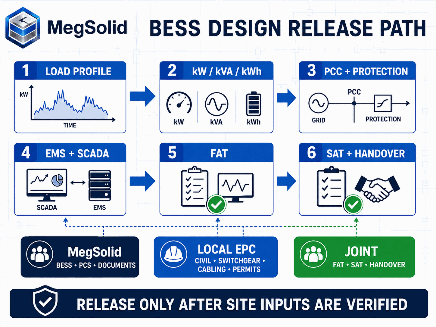
A project-specific BESS factory acceptance test should include, as applicable:
- model, serial number, firmware and drawing-revision verification;
- visual, mechanical, wiring and torque-record checks;
- insulation, protective earth and auxiliary-power checks;
- battery, PCS, HVAC or liquid-cooling, fire and emergency-stop alarms;
- charge and discharge operation at agreed test points;
- EMS mode, setpoint, limit, alarm and communication-loss tests;
- SCADA register and time-stamp verification;
- controlled punch-list and evidence package.
SAT should add the conditions that do not exist at the factory:
- CT ratio, polarity and PCC power direction;
- breaker, interlock, emergency-stop and protection trips;
- site communication paths and loss-of-signal behavior;
- peak-shaving or zero-export response at the actual meter;
- generator and ATS sequence where included;
- staged protected-load transfer and restoration;
- charge-recovery limit at the operating import boundary;
- capacity or performance test at the contractually defined AC point.
If a capacity test misses the target without an alarm, first check the test boundary, initial SOC, auxiliary loads, temperature, power level, voltage limits and early termination conditions. The troubleshooting method in BESS capacity-test analysis prevents a DC nameplate value from being compared with an uncorrected AC result.
Design Review Checklist Before Equipment Release
The following checklist is short enough for a design meeting and strict enough to stop a premature purchase:
- Duty: Peak shaving, backup, PV charging, generator support and export control priorities are ranked.
- Data: Meter interval, timestamp quality, missing data and seasonal basis are recorded.
- Power: Continuous kW, kVA, power factor, motor starts and overload duration are verified.
- Energy: AC delivery boundary, SOC window, losses, degradation and required end-of-life capacity are defined.
- Recovery: Available charging power and reserve-restoration deadline are calculated.
- Connection: PCC, voltage, fault level, transformer, switchboard, cable and earthing data are approved.
- Controls: Meter ownership, command priority, fail-safe state, alarms and SCADA points are issued.
- Environment: Temperature, altitude, humidity, dust, salt, water, noise and service access are checked.
- Safety: Model-specific reports and the applicable code matrix are available.
- Scope: Manufacturer, EPC, owner and utility responsibilities are assigned.
- Testing: FAT, SAT and capacity-test procedures use measurable acceptance criteria.
- Handover: Drawings, settings, firmware, manuals, spares, training and warranty conditions are listed.
A “no” on the checklist can still allow a budget number. It should stop final model release when the missing value can change architecture, warranty, the electrical interface or acceptance.
From Design Basis to a Purchasable C&I BESS
Do not start design from the largest battery the budget can carry. Start from a measurable duty and a clear boundary. Power, kVA and energy are calculated separately. The PCC, site conditions, control logic and acceptance test are then built around that duty.
This process gives procurement a defensible comparison. A cheaper cabinet that leaves out the meter, transformer, protection study, commissioning or usable-energy guarantee is not an equivalent offer. The same design basis also lets the EPC identify local construction work before equipment arrives.
For compact 400 V C&I duties, an ESSA cabinet is the logical first screen when its warranted power, energy and environmental limits cover the project. A liquid-cooled Energon system suits a different temperature, power-factor or operating profile after its kW capability is confirmed. Megawatt-class projects move to ESSC or 5000INTL architectures when their voltage and site interfaces fit the design basis. The final direction follows the verified site inputs, not the family name.
Compare MegSolid C&I BESS Configurations
Provide the design basis and mark any values that are still provisional. The comparison will state the preliminary equipment direction, the assumptions that remain open and the EPC interfaces that must be resolved before release.
FAQ
1. What information is needed to start a C&I BESS design?
Start with interval load data, a protected-load schedule, the single-line diagram, transformer and switchboard data, site voltage and power factor, environmental conditions, generator and PV information, and the required operating modes. Preliminary screening can begin with assumptions, but each assumption that affects product selection must be marked for confirmation.
2. Should a BESS be sized in kW or kWh first?
Both are required, and neither replaces the other. kW and kVA determine whether the PCS can carry the load and manage reactive power. kWh determines duration. Check transient starts and overload duty separately from both.
3. What is the difference between kW and kVA in BESS design?
kW is active power delivered to the load. kVA is apparent power and determines AC current at a given voltage. A load requiring 100 kW at 0.8 power factor draws 125 kVA, before any additional design margin or transient requirement.
4. Can nominal battery kWh be used as backup runtime?
No. Runtime depends on the usable SOC window, AC conversion losses, auxiliary consumption, discharge power, temperature, voltage limits and required end-of-life capacity. Use warranted usable AC energy when available and keep the measurement boundary consistent.
5. How is peak-shaving power calculated?
Subtract the agreed import target from the measured site demand at the PCC, then check meter interval, faster peaks, control latency, reactive-power duty and margin. The controller must also have enough SOC available when the peak occurs.
6. Why can BESS charging create another demand peak?
Charging adds to site import. If the recovery setpoint ignores concurrent facility demand, the combined load can exceed the demand target. Calculate permitted charging power from the import limit, live facility demand and an engineering margin.
7. Does a 125 kVA PCS provide 125 kW?
Only at unity power factor and within all other operating limits. At 0.8 power factor, 125 kVA corresponds to 100 kW. Use the project power factor and the controlled PCS capability curve.
8. Can a 400 V BESS connect directly to an existing switchboard?
Only after confirming bus and breaker ratings, short-circuit duty, protection coordination, cable capacity, earthing, spare-way arrangement and the connection authority's requirements. Matching nominal voltage is necessary but not sufficient.
9. Where should the PCC meter and CTs be installed?
They should be installed at the electrical boundary the BESS is required to regulate. The CT ratio, class, burden, polarity and communication path must support the required accuracy and response. The location belongs on the approved single-line diagram.
10. Is an IP54 cabinet automatically suitable outdoors?
No. IP54 addresses a defined level of ingress protection. It does not establish full-power capability at high temperature or altitude, condensation control, salt-mist resistance, acoustic compliance, flood protection or the required filter-maintenance interval.
11. What is the difference between FAT and SAT for a BESS?
FAT verifies the manufactured equipment, documented configuration and factory-testable logic before shipment. SAT verifies installation-specific wiring, meters, breakers, protection, communications and operating sequences at the project site.
12. Which party is responsible for BESS installation?
The signed contract controls. In a typical equipment-supply arrangement, the manufacturer supplies the BESS, controlled interface documents and agreed FAT support. The local EPC completes civil works, switchgear, cables, permits, site installation and local engineering, with joint SAT and handover activities.
13. How should ESSA, Energon and containerized BESS options be compared?
Compare warranted power at project temperature, altitude and power factor; usable AC energy; voltage architecture; cooling; environmental limits; protection and controls; installation scope; acceptance evidence and lifecycle service requirements. Nominal kWh alone cannot establish equivalence.
