 Skip to content
A pump or compressor start can trip production while a full battery sits behind an undersized converter. Use the MegSolid MEGA PCS range for the residual kW and kVA your source cannot carry; evaluate ESSA0100B-0215 (100 kW) only when the complete event fits its boundary. Share the start recording and source rating so the proposal addresses the trip you need to stop.
For factories, mines, pump stations and refrigerated warehouses, this short power surge can cause voltage sag, generator overload, contactor dropout or a complete production-line trip.
MegSolid evaluates these projects by separating three requirements:
- Motor starting demand
- Available grid or generator contribution
- Residual power that the BESS must supply
A 100kW motor does not automatically require a 100kW BESS.
Motor nameplate power describes normal operation. It does not show the full starting-current demand, acceleration time or reactive-power requirement.
The PCS must therefore be selected before the battery capacity is finalized.
Need a Preliminary Motor Starting BESS Assessment?
Submit the following project data:
| Required Information | Example |
|---|---|
| Motor rated power and voltage | 250kW, 400V |
| Starting method | Direct-on-line, VFD or soft starter |
| Starting current | Locked-rotor current or current multiple |
| Acceleration time | Seconds from start to rated speed |
| Electrical source | Grid, transformer or diesel generator |
| Existing voltage sag | Minimum measured bus voltage |
| Site architecture | Single-line diagram |
| Backup requirement | Required operating time after an outage |
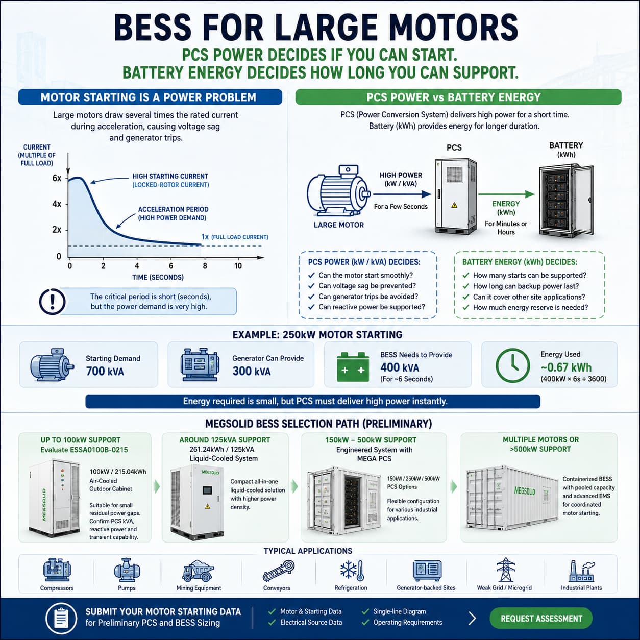
The Direct Answer: Can a BESS Support a Large Motor?
Yes, but only when the PCS and battery are engineered for the actual starting event.
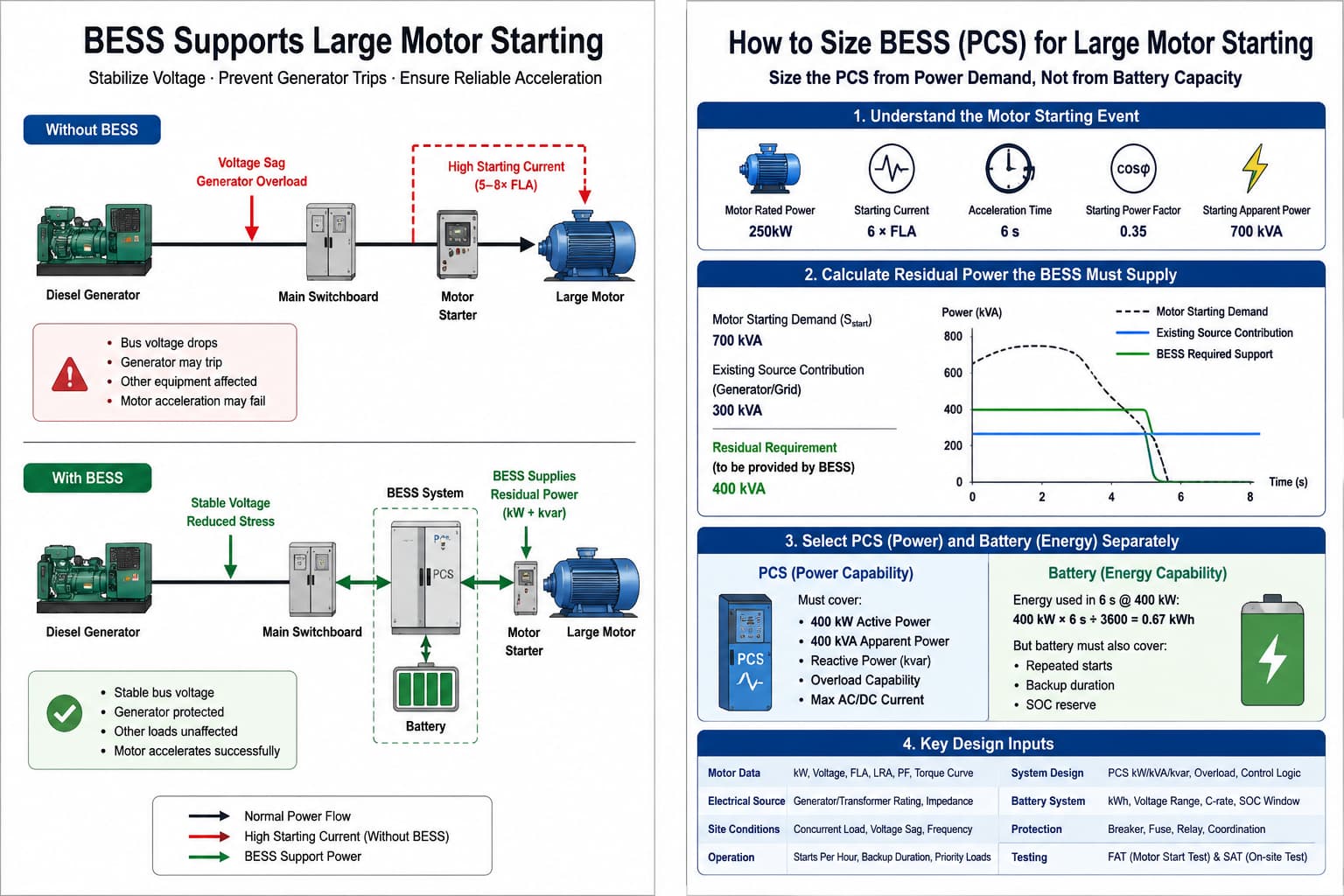
The BESS does not always need to supply the entire motor demand. It normally supplies the difference between the motor requirement and the power that the existing source can safely provide.
For example, a diesel generator may support the motor during normal operation but fail during acceleration.
The BESS can temporarily supply the remaining active and reactive power. This reduces the transient burden on the generator and stabilizes the facility bus.
However, BESS is not the correct solution for every project.
A VFD, soft starter, transformer upgrade or revised motor-start sequence may solve the problem at a lower cost.
The engineering assessment must identify the root cause before equipment is selected.
Why Large Motors Cause Voltage Sag
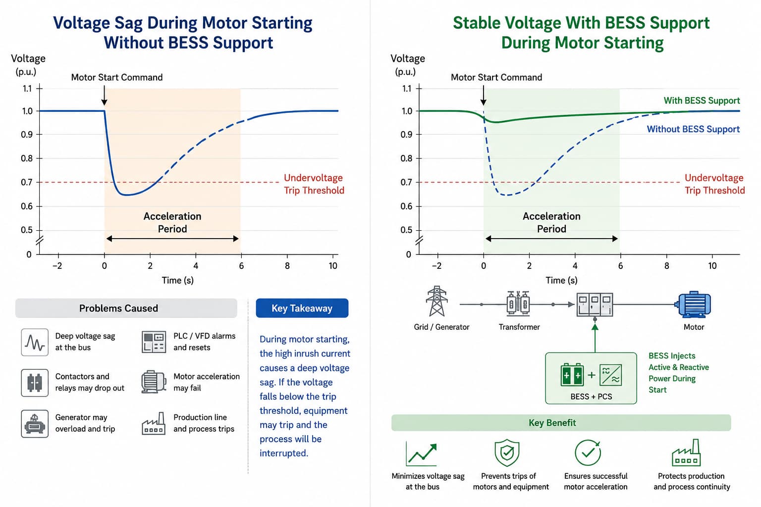
An induction motor can draw several times its normal current during startup.
This high current flows through:
- The transformer
- The generator
- The switchgear
- The cables
- The facility bus
Every component adds electrical impedance.
The result is a temporary voltage drop at the motor and across the facility electrical system.
A moderate voltage sag may only slow acceleration. A deeper sag can cause:
- Contactors to release
- PLCs to restart
- VFDs to report undervoltage
- Protection relays to operate
- Diesel generators to overload
- Other production equipment to trip
The severity of the sag depends on more than motor kW.
Engineers must also review:
- Locked-rotor current
- Starting power factor
- Acceleration time
- Load torque
- Transformer impedance
- Generator transient response
- Cable length and size
- Concurrent facility load
This is why motor-starting projects require a dynamic electrical assessment rather than a simple battery-capacity calculation.
When Should an EPC Evaluate BESS?
BESS is worth evaluating when the existing electrical source can support normal operation but cannot safely cover the startup peak.
Common project conditions include:
- A compressor starts while the factory is already near its transformer limit
- A mine motor causes a weak feeder to fall below the permitted voltage
- A pump-station generator trips during direct-on-line starting
- Multiple refrigeration compressors start within the same period
- A remote microgrid cannot justify a permanently oversized generator
- A factory requires both motor-start support and outage backup
These projects are power-dominant.
The difficult requirement lasts for seconds, not hours. The BESS must deliver high power quickly, even though the total energy used may be small.
BESS becomes more commercially attractive when it also performs:
- Backup power
- Peak shaving
- Solar self-consumption
- Diesel optimization
- Microgrid stabilization
If motor starting is the only requirement, a VFD or soft starter may provide a better lifecycle cost.
BESS vs. VFD, Soft Starter and Grid Upgrades
The correct solution depends on the motor, process and existing electrical infrastructure.
| Engineering Option | Best-Fit Application | Main Limitation |
|---|---|---|
| Direct-on-line starter | Small motor on a strong grid | Highest starting current |
| Star-delta starter | Reduced starting torque is acceptable | May not reduce current enough |
| Soft starter | Fixed-speed motor requiring a controlled ramp | Does not provide backup power |
| VFD | Controlled acceleration and variable-speed operation | Requires harmonic and bypass review |
| Capacitor bank | Mainly reactive-power deficiency | Cannot supply a major active-power deficit |
| Transformer upgrade | Permanent site-load growth | Civil and electrical upgrade costs |
| Larger generator | Permanent off-grid power requirement | Higher fuel use at low load |
| BESS | Short power deficit plus resilience requirement | PCS transient capability must be verified |
| BESS plus VFD | Weak grid and critical process load | More complex system coordination |
A BESS should not be presented as the universal answer.
A professional supplier should first determine whether the project needs:
- More starting torque
- Lower starting current
- Additional active power
- Reactive-power support
- A stronger transformer or generator
- Backup power after motor startup
Size the PCS Before the Battery
The most common procurement error is selecting battery kWh before calculating PCS power.
These parameters perform different functions.
Battery energy in kWh determines how long the system can continue supplying power.
PCS active power in kW determines how much real power the system can deliver.
PCS apparent power in kVA limits the combined active and reactive output.
Reactive power in kvar affects motor acceleration and bus-voltage support.
The starting apparent power can be estimated using:
Sstart = √3 × V × Istart ÷ 1,000
The starting active power is:
Pstart = Sstart × Starting Power Factor
The reactive-power requirement is:
Qstart = √(Sstart² − Pstart²)
These calculations provide a preliminary estimate.
The final model must also include the contribution from the grid, transformer or generator.
Example: A Power-Dominant Motor Starting Event
Assume an industrial motor requires 700kVA during startup.
The existing generator can safely provide 300kVA without exceeding its transient limit.
A 400 kVA residual is a preliminary screen only if the motor and safe generator contribution use compatible power-factor and transient assumptions. Model the remaining active and reactive power, current, voltage recovery and acceleration together; subtracting two kVA nameplates does not by itself select the PCS. Use the recorded motor/source waveforms or an approved dynamic study to release the actual support requirement.
| Parameter | Illustrative Value |
|---|---|
| Motor starting demand | 700kVA |
| Safe generator contribution | 300kVA |
| Residual BESS requirement | 400kVA |
| Acceleration time | 6 seconds |
If the BESS supplies 400kW for six seconds, the theoretical energy used is:
400kW × 6 ÷ 3,600 = 0.67kWh
The energy requirement is very small.
The PCS requirement is not.
A 215kWh battery connected to a 100kW PCS cannot deliver 400kW simply because the battery contains enough stored energy.
The project must verify:
- PCS rated power
- Maximum apparent power
- Reactive-power capability
- Temporary overload rating
- Maximum AC current
- Maximum DC current
- Minimum permitted SOC
- Battery temperature limits
The BMS may reduce available discharge power when SOC, temperature or DC voltage approaches an operating limit.
Catalogue battery energy therefore does not prove that the complete system can support the motor.
What Information Is Required for PCS Sizing?
An EPC should not request a quotation using motor nameplate power alone.
The supplier needs enough data to model the full electrical event.
| Required Data | Engineering Purpose |
|---|---|
| Rated motor power | Defines normal operating demand |
| Rated voltage and frequency | Defines the electrical interface |
| Full-load current | Establishes the operating baseline |
| Locked-rotor current | Estimates starting-current demand |
| Starting power factor | Separates active and reactive requirements |
| Starting method | Changes current and torque characteristics |
| Acceleration time | Defines transient duration |
| Load torque curve | Identifies stall risk |
| Starts per hour | Affects thermal loading and SOC recovery |
| Concurrent facility load | Defines remaining source capacity |
| Transformer rating | Defines upstream capacity |
| Transformer impedance | Determines expected voltage drop |
| Generator rating | Establishes continuous power |
| Generator load-step curve | Defines transient contribution |
| Minimum acceptable voltage | Sets the bus-voltage target |
| Single-line diagram | Identifies connection and protection points |
| Backup duration | Determines battery energy requirement |
Measured voltage and current waveforms are especially useful.
Where site measurements are unavailable, the EPC should provide motor, generator, transformer and cable data for preliminary modelling.
Preliminary MegSolid Product Selection Path
The following table is an initial procurement direction.
It does not guarantee that a specific model can start a specific motor.
| Calculated Residual Requirement | Preliminary Product Direction |
|---|---|
| Up to 100kW active-power support | Evaluate ESSA0100B-0215 and verify PCS kVA, current and transient capability |
| Around 125kVA support | Evaluate the 261.24kWh / 125kVA liquid-cooled system |
| 150–500kW support | Evaluate an engineered battery system with a 150kW, 250kW or 500kW MEGA PCS |
| Multiple motors or above 500kW | Evaluate pooled containerized BESS and sequential motor-start control |
| Motor support plus backup | Size PCS from startup demand and battery capacity from backup duration |
ESSA0100B-0215 Outdoor C&I Cabinet
The ESSA0100B-0215 is an intelligent air-cooled outdoor C&I energy storage cabinet.
| Parameter | Verified Value |
|---|---|
| Rated AC power | 100kW |
| Nominal battery energy | 215.04kWh |
| Battery configuration | 1P240S |
| Nominal battery voltage | 768V |
| Battery voltage range | 672–850V |
| Cooling | Intelligent air cooling |
| Enclosure | IP54 |
| Operating temperature | 0–45°C |
| Net weight | 3,900kg |
This system may be evaluated for smaller residual power gaps.
It must not be selected only because the motor is rated at or below 100kW.
The PCS current, kVA, overload curve and reactive-power range must still be confirmed.
Review the 100kW 215kWh Outdoor C&I Energy Storage System for model-specific information.
261.24kWh Liquid-Cooled C&I System
The 261.24kWh system is rated at 125kVA.
It can be considered where the project requires higher apparent power than a standard 100kW cabinet can provide.
| Parameter | Verified Value |
|---|---|
| Rated energy | 261.24kWh |
| Rated AC power | 125kVA |
| Cell chemistry and capacity | LFP, 314Ah |
| Battery configuration | 1P260S |
| Nominal DC voltage | 832V |
| DC voltage range | 676–936V |
| Adjustable power factor | -1 to +1 |
| Cooling | Liquid cooling |
| Operating temperature | -20–55°C, derated above 45°C |
The EPC must still confirm temporary overload and motor-starting current capability.
The 261.24kWh product should not be described as hybrid solid-state unless model-specific evidence is available.
MEGA PCS for Higher-Power Projects
MegSolid MEGA PCS options include:
| Model | Rated Power | Maximum Apparent Power |
|---|---|---|
| MEGA0100TS | 100kW | 110kVA |
| MEGA0150TS | 150kW | 165kVA |
| MEGA0250TS | 250kW | 275kVA |
| MEGA0500TS | 500kW | 550kVA |
The series supports adjustable power factor from 1 lagging to 1 leading.
Grid-current THD is listed as below 3%.
The PCS also supports automatic on-grid and off-grid operation.
The published overload capability is 110% long-term. However, the supplier must still confirm whether this is suitable for the actual motor-starting profile.
Review the MegSolid MEGA PCS technical specifications before freezing the system configuration.
The Control Sequence Matters
A motor-support BESS should not wait for the facility voltage to collapse before responding.
The motor starter, PLC and EMS should exchange a coordinated start command.
A typical sequence is:
- The PLC sends a motor-start request.
- The EMS checks battery SOC, temperature and PCS availability.
- The PCS enters the required support mode.
- The starter or VFD receives permission to start.
- The PCS supplies the required active and reactive power.
- PCS output reduces as the motor reaches operating speed.
- The BESS restores its reserved SOC before the next start.
This sequence avoids delayed response.
It also prevents a motor-start command when the battery cannot provide the required power.
The BMS, PCS and EMS must continuously exchange operating limits.
A communication failure should place the system in a defined safe state.
The BMS and EMS communication architecture guide explains how these controls should be coordinated.
Motor Starting Must Be Included in FAT
A generic battery charge-and-discharge test does not prove that the BESS can support a large motor.
The FAT should include an application-specific transient test.
Factory Acceptance Test Requirements
The witnessed FAT should verify:
- Rated active-power output
- Maximum apparent-power output
- Reactive-power response
- Temporary overload capability
- Maximum AC and DC current
- BMS discharge-permission logic
- SOC reserve control
- Simulated motor-start command
- Step-load response
- Voltage and frequency recovery
- Communication-loss response
- Generator synchronization logic
- Alarm and shutdown functions
The test procedure should define the measurement point and acceptance criteria.
A supplier should not describe a successful steady-state discharge test as proof of motor-starting performance.
Use the BESS Factory Acceptance Testing guide to develop the witnessed test scope.
Site Acceptance Test Requirements
The SAT should use the actual motor and electrical source.
Record:
- Pre-start bus voltage
- Minimum voltage during acceleration
- Voltage-recovery time
- Motor acceleration time
- Grid or generator current
- BESS active-power output
- BESS reactive-power output
- Battery SOC change
- PCS DC current
- Protection and alarm status
The test should be performed under a realistic site load.
Testing the motor while the rest of the facility is unloaded may hide the actual project risk.
Repeated-start testing should also be included when the process requires several starts per hour.
Cabinet or Containerized BESS?
A modular cabinet may be suitable when the residual power gap is limited.
It may also suit projects where motors are distributed across several low-voltage load centres.
A containerized system is usually more appropriate when:
- Several large motors must be coordinated
- PCS power exceeds individual cabinet ratings
- Long-duration backup is required
- Medium-voltage connection is planned
- Future expansion is expected
- Redundant PCS architecture is required
- Centralized SOC management is preferred
The choice should be based on electrical architecture, not only installation footprint.
Review the modular cabinet versus containerized BESS comparison before selecting the physical system format.
What Should an EPC Submit to MegSolid?
A complete RFQ allows the engineering team to provide a useful configuration.
A request containing only “250kW motor” is not sufficient.
Submit:
- Project location
- Maximum and minimum ambient temperature
- Motor datasheet
- Starting method
- Starting-current data
- Acceleration time
- Transformer datasheet
- Generator datasheet
- Single-line diagram
- Concurrent facility load
- Existing voltage-sag measurements
- Required starts per hour
- Required backup duration
- Available installation area
- Target commissioning date
MegSolid can then determine whether the project should evaluate:
- A 100kW outdoor cabinet
- A 125kVA liquid-cooled system
- A higher-power MEGA PCS configuration
- A pooled containerized BESS
- A BESS combined with a VFD or revised starting sequence
Review the MegSolid commercial and industrial energy storage solutions for wider application options.
Final Procurement Recommendation
A motor-starting BESS should be purchased as a coordinated power-quality system.
It should not be selected from a battery-capacity table alone.
The correct procurement process is:
- Calculate the motor-starting demand.
- Determine the safe contribution from the existing source.
- Size the PCS for the residual kW, kVA and kvar requirement.
- Size the battery for repeated starts and backup duration.
- Coordinate the BMS, PCS, EMS, starter and generator.
- Verify the complete system through FAT and SAT.
A project that submits only motor kW will receive an unreliable estimate.
Send MegSolid the motor-start curve, existing source limits, concurrent production load, single-line diagram and permitted bus-voltage/interruption window. Ask the offer to return the selected PCS kW / kVA/current envelope, battery reserve and recharge duty, starter/PLC/EMS sequence, measured acceptance limits and installation/service split. That gives the factory a configuration and test plan for technical and commercial evaluation, rather than a larger battery that still cannot start the process.
FAQ
Q1: Can a BESS start a large induction motor?
A BESS can support a large induction motor when the PCS has sufficient kW, kVA, reactive-power and transient-current capability.The motor-start curve and electrical source must be evaluated first.
Q2: Is a 100kW BESS suitable for a 100kW motor?
Not automatically. A 100kW motor may require several times its normal current during acceleration. The PCS must be selected from the residual starting demand, not the motor nameplate alone.
Q3: Why is kWh not the main parameter?
Motor starting usually lasts only a few seconds.The energy consumed may be small, but the required PCS power and current can be high.
Q4: What is the difference between PCS kW and kVA?
kW represents active power.kVA represents the combined active and reactive output handled by the converter. Both can be important during motor acceleration.
Q5: Can BESS work with a soft starter?
Yes.The soft starter reduces starting current, while the BESS supports the remaining power deficit. Their ramp rates and control signals must be coordinated.
Q6: Can BESS work with a VFD?
Yes.A BESS can stabilize the electrical source supplying the VFD. Harmonics, regeneration, bypass operation and protection settings must still be reviewed.
Q7: Can BESS prevent a diesel generator trip?
It can reduce the transient burden on the generator.The final result depends on generator AVR response, governor response, short-circuit capability and the remaining site load.
Q8: How much SOC should be reserved?
The reserve depends on starting power, event duration, repeated starts and required backup time.The EMS should block the start command if the required reserve is unavailable.
Q9: What voltage sag is acceptable?
The permitted sag depends on the motor, starter, PLCs, contactors and other sensitive loads.The project engineer should define the minimum acceptable bus voltage.
Q10: What information is required for a quotation?
Submit the motor datasheet, starting method, starting current, acceleration time, source rating, transformer impedance, single-line diagram and backup requirement.
Q11: What type of BESS is best for large motor starting?
The best system is one with a PCS sized for the residual motor-starting kW, kVA and reactive-power requirement.Battery capacity is then selected for repeated starts and backup duration.
Q12: How does BESS reduce voltage sag?
The PCS injects active and reactive power during motor acceleration.This reduces the temporary demand placed on the transformer, grid feeder or diesel generator.
Q13: What should an EPC send to a BESS supplier?
The EPC should send the motor curve, starting method, source rating, transformer impedance, single-line diagram, measured voltage sag and required operating sequence.
