
When a facility has only a 120/240V single-phase generator or constrained utility source but its pumps, compressors and production equipment require 400V three-phase power, the solution is not simply “buy a larger inverter.” The design must separate single-phase charging from three-phase grid formation, then size the battery around the maximum state-of-charge downturn and the available recovery window.
| Engineering decision | Result |
|---|---|
| Architecture decision | Use an independent, current-limited AC/DC rectifier feeding a shared DC bus, plus a verified grid-forming PCS for the three-phase output. |
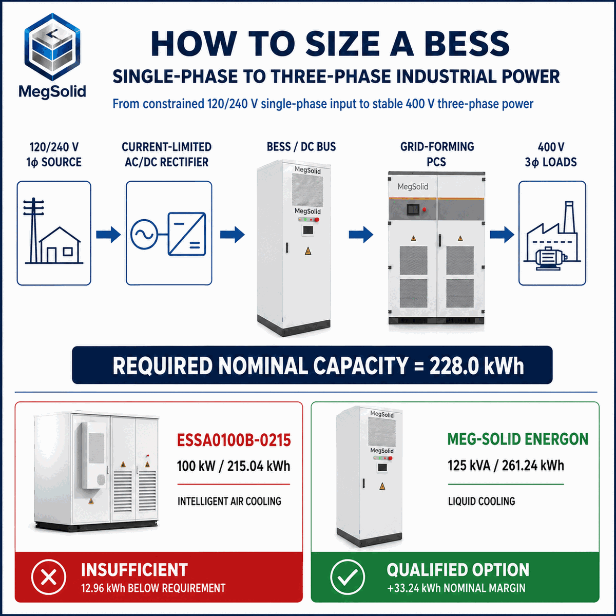
| Energy decision | The illustrated duty requires 228.0 kWh nominal capacity after the SOC window, cold derating and end-of-life retention are applied. |
| Product screen | The 215.04 kWh cabinet does not clear the calculated requirement; the 261.24 kWh platform provides 33.24 kWh of nominal margin. |
| Release condition | Final procurement still depends on generator, rectifier, PCS, motor-start, protection, thermal and certification data. |
Is your single-phase source strong enough for the proposed rectifier?
Send the generator nameplate, breaker rating and 24-hour load profile for a preliminary feasibility review.
Dual-Port DC-Coupled Topology for Phase Conversion
Many standard single-port PCS units are not designed to accept a single-phase AC charging source while simultaneously forming an independent three-phase island. In the architecture evaluated here, the 120/240V single-phase generator connects to a dedicated AC/DC rectifier. The rectifier limits input current and feeds the shared DC bus. The battery buffers the difference between source power and load power, while the main MegSolid 30–500kW Power Conversion System forms the 400V three-phase output.
This functional separation decouples industrial loads from source-side voltage and frequency disturbance. The selected PCS model must explicitly support the intended off-grid/grid-forming mode, 3W+N+PE output, unbalanced-load duty, motor-start kVA, overload duration and protection logic. See the deeper PCS and grid-forming engineering guide before assuming that every bidirectional inverter can perform this role.
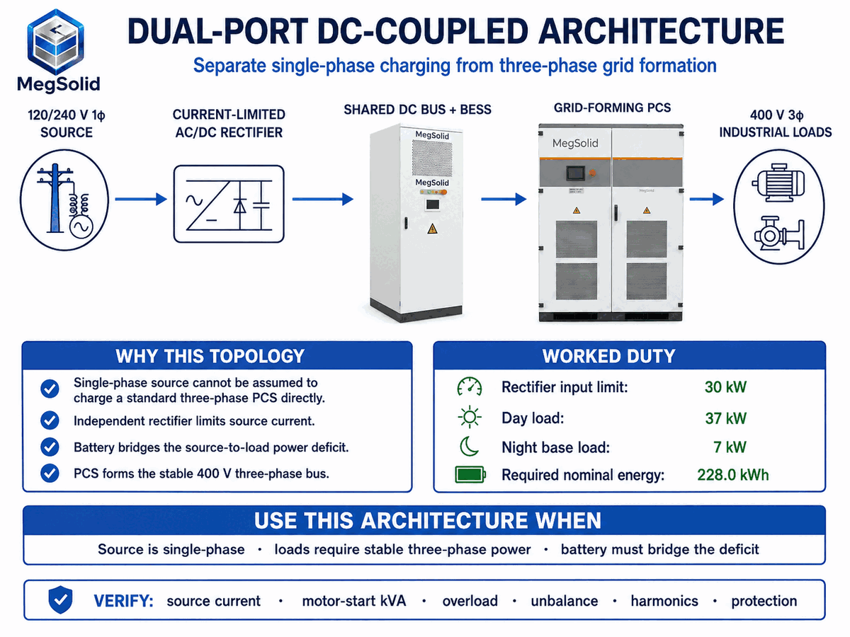
System topology: Single-phase generator or grid → current-limited AC/DC rectifier → shared DC bus and battery → grid-forming DC/AC PCS → 400V three-phase industrial loads.
Four engineering boundaries that must be verified
- Single-phase input current: The rectifier must cap current below the generator and breaker limit after power factor, harmonics, altitude, ambient temperature and transient margins are considered.
- Three-phase power quality: Voltage unbalance, THDu, frequency regulation and negative-sequence current capability must be verified for the chosen PCS model and actual phase loading.
- Galvanic isolation and earthing: A built-in or external transformer may provide isolation, but the neutral/earthing scheme, DC injection, fault current and protective-device coordination remain project-specific.
- Diesel interaction: Minimum generator loading, reverse-power protection, governor response, start/stop authority and loss-of-communications behavior must be defined. Use the BESS and diesel generator control guide as an RFQ checklist.
Sizing the BESS: Continuous Load, Motor Start and Energy Recovery
A phase-conversion BESS has two independent ratings: power and energy. PCS power must cover the maximum coincident kVA, including motor starting and reactive demand. Battery energy must cover the maximum cumulative deficit before the recovery period starts. Heavy motors such as the illustrated 22kW water pump should use a VFD or soft starter, with start kVA taken from the actual motor and starter datasheets rather than a generic multiplier.
Required nominal capacity = (147.96 kWh + 8.0 kWh) ÷ (0.90 × 0.95 × 0.80) = 228.0 kWh
The calculation uses the maximum SOC downturn, not the smaller daily net energy balance. That distinction prevents a system from appearing sustainable over 24 hours while still exceeding its usable capacity during the 14-hour daytime interval.
Capacity Decision: 215.04 kWh vs 261.24 kWh
MegSolid publishes the ESSA0100B-0215 air-cooled C&I system at 100kW and 215.04kWh using 280Ah LFP cells in a 1P240S configuration. Because 215.04kWh is below the 228.0kWh screen, one cabinet is insufficient under the stated assumptions.
The corresponding Meg-Solid Energon 261.24kWh liquid-cooled C&I system is published at 125kVA, 261.24kWh, 314Ah LFP and 1P260S, with an 832V nominal DC platform and 676–936V operating range. It clears the screen by 33.24kWh of nominal capacity.
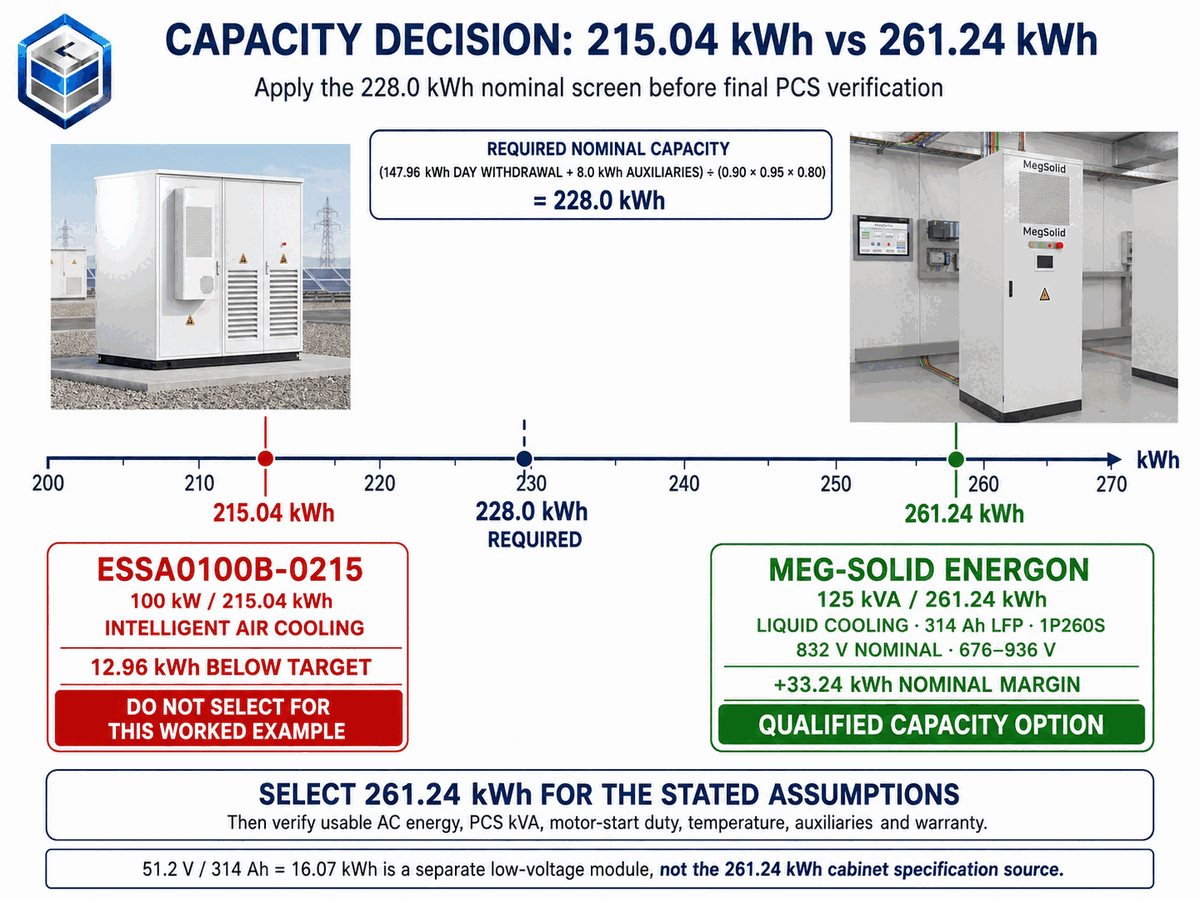
Corrected product-reference boundary: The 261.24kWh high-voltage C&I system must be supported by its own system page and project datasheet. MegSolid’s separate 51.2V/314Ah product is a 16.07kWh low-voltage battery module; it is not the datasheet for the 832V, 1P260S C&I cabinet. The shared 314Ah capacity does not make the two products electrically interchangeable.
For a line-by-line procurement comparison, use the 215kWh vs 261kWh commercial battery storage guide and the 261kWh liquid-cooled system RFQ guide.
Turn the screening calculation into a project quotation
Provide one-second or faster motor-start data where available, the 24-hour load profile and the required reserve SOC.
Battery Chemistry and Thermal Platform: What the Buyer Must Verify
The 215.04kWh cabinet and the 261.24kWh cabinet differ in more than nominal energy. The former is listed with 280Ah LFP cells and intelligent air cooling; the latter uses a 314Ah LFP, 1P260S configuration and liquid cooling. For broader product context, review the MegSolid C&I energy storage portfolio.
Do not infer propagation performance, cycle warranty or insurance treatment from the words “hybrid solid-state” alone. Request cell-level chemistry documentation, the system BOM, model-specific certification scope, thermal design, fire-protection drawings and relevant test reports. The solid-state vs liquid LFP datasheet comparison explains which claims require independent evidence.
The 261.24kWh product page lists a maximum system efficiency of 90%. That value must not automatically be interpreted as AC-to-AC round-trip efficiency. Confirm the measurement boundary, SOC window, charge and discharge power, temperature, auxiliary consumption, transformer losses and battery state of health in the project test plan.
Illustrative Ontario Load Profile and SOC Recovery
Consider an Ontario manufacturing facility using a 120/240V single-phase 60kVA diesel generator to support a VFD-equipped 22kW water pump and a 15kW HVAC compressor. During the 14-hour production window, the 37kW load produces an estimated 10.04kW DC-bus deficit after the stated conversion assumptions. During the 10-hour night period, the 7kW base load leaves approximately 21.21kW of DC-bus surplus for recovery.
At an idealized 21.21kW net DC recovery rate, replacing the 147.96kWh daytime withdrawal takes roughly seven hours before charging taper, thermal limits and control reserves. The EMS should reduce or stop rectifier output as the upper SOC limit is approached, while maintaining the facility’s 7kW nighttime load and respecting minimum generator loading. Review the BMS and EMS communication architecture when defining those commands and fail-safe states.
Harmonics, Safety and Compliance Boundaries
VFDs and other non-linear loads can distort the newly formed microgrid. A single THDi number is not enough to demonstrate IEEE 519 performance at the point of common coupling: the study must consider TDD, harmonic order, the Isc/IL ratio, source impedance and the actual measurement boundary. The PCS page publishes rated-condition performance, but the site acceptance test must represent the real generator, rectifier and load combination.
High-power C&I systems also need smoke, temperature and off-gas detection, fire-protection logic, isolation, emergency stops and coordinated shutdown sequences. Use the BESS thermal-runaway prevention guide and the UL 9540A and IEC 62619 engineering guide to define the evidence package. UL 9540A is a test method; it is not the same as the UL 9540 system certification.
The 400V output must also be coordinated with the facility switchboard, protective devices and earthing system. The 400V BESS switchboard connection guide provides the next-stage electrical checklist.
RFQ Inputs Required Before Final Selection
- Source package Generator nameplate, continuous kW/kVA, breaker, voltage, frequency, governor/AVR data, allowable harmonics and minimum loading.
- Load package One-line diagram, 24-hour kW/kVA profile, phase allocation, motor/VFD datasheets, start sequence and critical-load priorities.
- Site package Ambient range, altitude, indoor/outdoor location, access, foundation, cable distance, noise limit and fire separation.
- Acceptance package Required codes, utility/AHJ conditions, FAT/SAT tests, usable AC energy, overload duration, THD/TDD and warranty boundary.
Get a phase-conversion BESS proposal based on your real duty cycle
MegSolid can map the rectifier limit, PCS duty, battery capacity, thermal design and EMS interlocks into one project-specific scope.
FAQ
Can a standard three-phase PCS charge directly from a single-phase generator?
Not by assumption. Many PCS products expect a compatible three-phase AC connection or a DC battery source. If the system must charge from 120/240V single-phase power while forming a separate 400V three-phase bus, specify and validate an independent AC/DC rectifier or another manufacturer-approved input stage.
Why is an independent rectifier used in this architecture?
It converts the single-phase source to a controlled DC input and limits current so the generator does not stall or trip. It also separates source-side frequency and voltage disturbance from the PCS that forms the three-phase load bus.
How was the 228.0 kWh nominal requirement calculated?
The model adds the 147.96kWh maximum daytime battery withdrawal and 8.0kWh of auxiliaries, then divides by a 90% SOC window, 95% cold derating factor and 80% end-of-life retention: 155.96 ÷ 0.684 = 228.0kWh.
Is one 215.04 kWh cabinet enough for this duty cycle?
No under the stated assumptions. Its nominal energy is 12.96kWh below the 228.0kWh screening requirement, before project-specific usable-AC-energy and reserve requirements are contractually confirmed.
Why is the 261.24 kWh system selected?
Its published nominal capacity exceeds the 228.0kWh screen by 33.24kWh. It also provides a 125kVA power platform and liquid cooling, but final selection still requires confirmation of usable energy, PCS behavior, temperature performance and warranty limits.
Is the 51.2V 314Ah battery module the same product as the 261.24 kWh cabinet?
No. The low-voltage module is a 51.2V, 16.07kWh product. The C&I cabinet is a high-voltage 1P260S system with 832V nominal DC and 261.24kWh rated energy. A shared 314Ah figure does not make their datasheets interchangeable.
How should the PCS power rating be selected?
Use maximum coincident apparent power, not only running kW. Include motor-start kVA, power factor, reactive-power duty, unbalanced loading, harmonic current and the manufacturer’s overload duration at the project temperature and altitude.
Are VFDs or soft starters required for the motors?
They are strongly recommended for large motors in this limited-source scenario. The final requirement depends on direct-on-line start current, PCS overload capability, generator response, process torque and the simultaneous running loads.
Can a 60kVA single-phase generator safely feed a 30kW rectifier?
Possibly, but the nameplate kVA alone is insufficient. Verify continuous real-power rating, breaker current, rectifier power factor and harmonic current, ambient/altitude derating, minimum loading, transient response and the generator manufacturer’s permitted non-linear load.
How long does nighttime SOC recovery take?
At the illustrated 21.21kW net DC surplus, replacing 147.96kWh takes about seven hours before charging taper and other control limits. Actual recovery time depends on the charge curve, temperature, auxiliaries, upper SOC reserve and generator availability.
What should happen when the battery reaches its upper SOC limit?
The EMS should taper or stop rectifier charging, maintain the nighttime facility load and keep the generator inside its permitted loading range. It must also define safe behavior if a meter, BMS, PCS or communications link fails.
Does the published 90% maximum system efficiency equal AC-to-AC round-trip efficiency?
Not without a defined test boundary. Ask whether PCS, transformer, battery, cooling, heating and auxiliary losses are included, and specify SOC, temperature, charge/discharge power and state of health for the acceptance test.
Does a low THDi reading prove IEEE 519 compliance?
No. IEEE 519 assessment at the PCC requires the applicable TDD limits, harmonic orders, Isc/IL ratio, measurement boundary and operating conditions. A single THDi value can support the study but does not replace it.
Can this architecture be used at an Ontario factory with a 120/240V generator?
It can be technically feasible, but the Ontario project must be reviewed against the actual generator, facility distribution, local electrical requirements, utility conditions where applicable and the authority having jurisdiction. The article’s Ontario case is an illustrative sizing scenario, not a permit-ready design.
What changes for a Northern Canada site operating at −5°C or colder?
Confirm the cabinet’s charging temperature limits, preheating logic, heater and liquid-cooling power, cold-soak recovery time, reduced usable energy and whether the stated output is derated. Include this auxiliary energy in both the daily balance and the maximum SOC downturn.
What should a Canadian EPC include in the RFQ for this phase-conversion BESS?
Include generator and rectifier data, the one-line diagram, time-series kW/kVA, motor starts, ambient and altitude, installation location, switchboard and earthing details, required approvals, fire-safety scope, FAT/SAT criteria, warranty duty cycle and delivery location.
Product evidence used in this revision: official MegSolid pages for the ESSA0100B-0215, the Meg-Solid Energon 261.24kWh system and the MEGA0030TS–MEGA0500TS PCS series. Product photos in all three article graphics are taken directly from those pages and have not been redrawn.
Engineering disclaimer: All load-flow, thermal, phase-unbalance and harmonic values described as illustrative or modeled are design inputs, not guaranteed field performance. Final results depend on the issued project datasheets, controls, protection design, installation, commissioning and acceptance-test boundary.