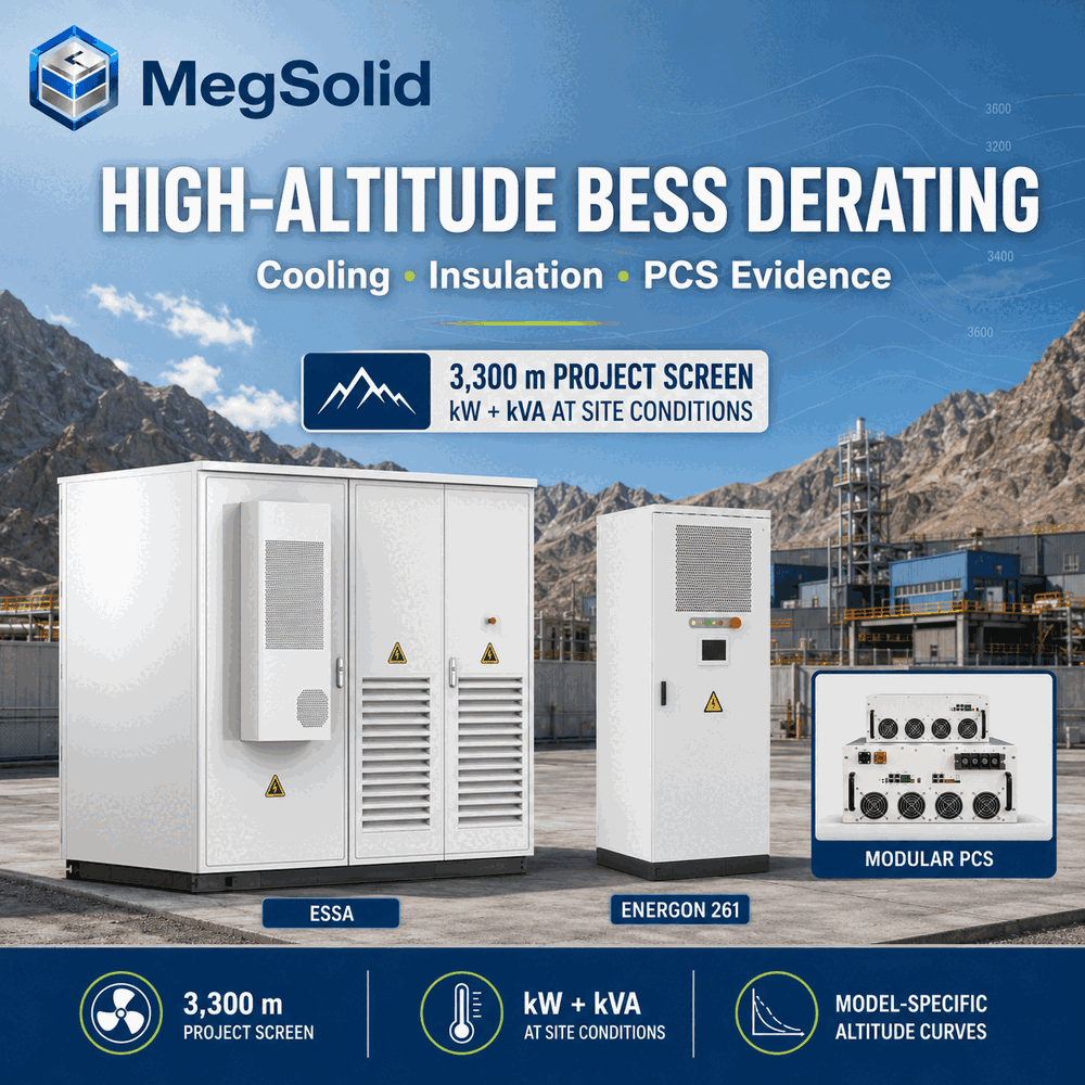
High-altitude BESS selection needs two independent approvals: continuous power at the surveyed elevation and intake temperature, and insulation suitability at the actual AC/DC voltage. A mine or mountain factory needing 92 kW cannot select from a 100 kW nameplate alone. Check available kVA, power factor, cooling and every component in the power path before freezing the single-line diagram.
Use the harsh-site battery-storage guide for the wider environmental screen. This article concentrates on elevation: available PCS power, heat rejection, electrical clearances and the evidence needed to accept the installed system. The MEGA transformer-integrated PCS is one equipment route; its curve must match the complete supplied configuration.
The quickest screening rule is:
Required continuous AC power ≤ warranted available AC power at the project altitude, temperature and power factor
A published maximum altitude defines the operating boundary. The warranted-power value on the right side of the inequality closes the purchase decision for the actual site.
What to lock before the single-line is frozen
- Record the installation elevation from the project survey instead of using the nearest city's altitude.
- Request the model-specific altitude curve, its test or calculation basis and every condition attached to it.
- Combine altitude, temperature, power factor and continuous duty in one operating point.
- Check air clearance and withstand evidence for the supplied voltage and elevation.
- Follow the heat path all the way to ambient air, including liquid-cooled systems.
- Reject a mixed equipment schedule where one component's altitude limit sits below the site elevation.
High-altitude BESS sizing requires the PCS altitude and temperature derating curves to be applied at the same operating point. Confirm the remaining kW and kVA at the required power factor, then check cooling capacity, air clearance, insulation coordination and transformer limits for the site elevation.
Why Altitude Changes Both Heat Removal and Electrical Stress
Air thins as elevation rises. A given volume of cooling air then carries less mass, so the same fan flow removes less heat than it does near sea level. Semiconductors, magnetics, capacitors and busbars run with less thermal margin. The controller answers with a controlled output cut, a temperature alarm or a trip at the defined boundary.
Reduced air density also changes insulation through air. IEC 60664-1:2020 covers insulation coordination within its scope of up to 1,000 V AC, 1,500 V DC and 30 kHz, with base provisions through 2,000 m and guidance for higher elevations. Use the edition, amendments and product standard specified for the actual equipment. Reducing PCS current does not automatically reduce its DC-link voltage or establish clearance compliance.
These effects reach different parts of the system:
| High-altitude effect | Equipment exposed | Evidence required |
|---|---|---|
| Reduced convective heat transfer | PCS heatsinks, fans, transformer, radiator, switchgear and auxiliaries | Temperature-rise evidence and available-power curve at project conditions |
| Reduced air dielectric strength | Busbars, terminals, contactors, breakers, fuses, surge devices and switchgear | Insulation-coordination calculation, clearances and withstand evidence |
| Lower fan mass flow for the same volumetric flow | Forced-air PCS, cabinet air paths and dry coolers | Fan/heat-exchanger selection at site air density |
| Combined temperature and altitude stress | Power semiconductors, magnetics and capacitors | One combined derating method, not two separate brochure limits |
| Remote, difficult service access | Filters, fans, pumps, coolant circuits and spares | Maintenance interval, alarm list, site spares and recovery procedure |
The wider site screen is covered in Commercial Battery Storage System for Harsh Sites. The sections below stay with altitude-specific power, cooling and insulation decisions.
Read Four Altitude Values Before Comparing Products
A datasheet can contain several altitude numbers that answer different questions. Procurement should label each one.
Full-power altitude
This is the highest elevation at which the supplier warrants the stated continuous power under the other defined conditions. Datasheets often label it as the derating threshold. If the document says “derating above 3,000 m,” the full-power assumption ends above that point.
Maximum operating altitude
This is the upper elevation boundary for operation. Output at that altitude can be below nameplate. A product marked “maximum altitude 5,000 m; derating above 3,000 m” has a 2,000 m operating band in which the controlled curve defines the reduced-power value.
Insulation-design altitude
This is the elevation used for clearance and withstand design. It needs to cover the complete equipment assembly and the supplied DC and AC voltages. A thermal limit alone gives no insulation evidence.
Site elevation
Use the BESS pad elevation from the project survey. A nearby town, airport or valley-floor figure can understate the actual installation elevation. Include the permitted survey tolerance where the site is close to a threshold.
Put the four values on one comparison sheet. Clearing the maximum-operating-altitude line only means the model stays inside its published elevation range. Available power and insulation still decide the configuration.
MegSolid Altitude Boundaries Are Model-Specific
The current MegSolid product reference gives different thresholds for the hybrid inverter, modular PCS, transformer-integrated PCS and cabinet platforms.
| Product or model | Published altitude boundary | Cooling and enclosure | Procurement consequence |
|---|---|---|---|
| R30KH3 / R40KH3 / R50KH3 | Maximum 4,000 m; derating above 2,000 m | Forced air, IP65 | Request the available kW and kVA curve above 2,000 m for the selected model |
| PMA080 / PMA0105 / PMA0125 | Maximum 5,000 m; derating above 3,000 m | Power compartment IP20, control compartment IP6X | Treat it as a PCS module requiring a project enclosure and cooling design |
| MEGA0030TS–MEGA0500TS | Maximum 5,000 m; derating above 3,000 m | Forced air, IP21, built-in isolation transformer | Request combined altitude/temperature power and transformer temperature-rise evidence |
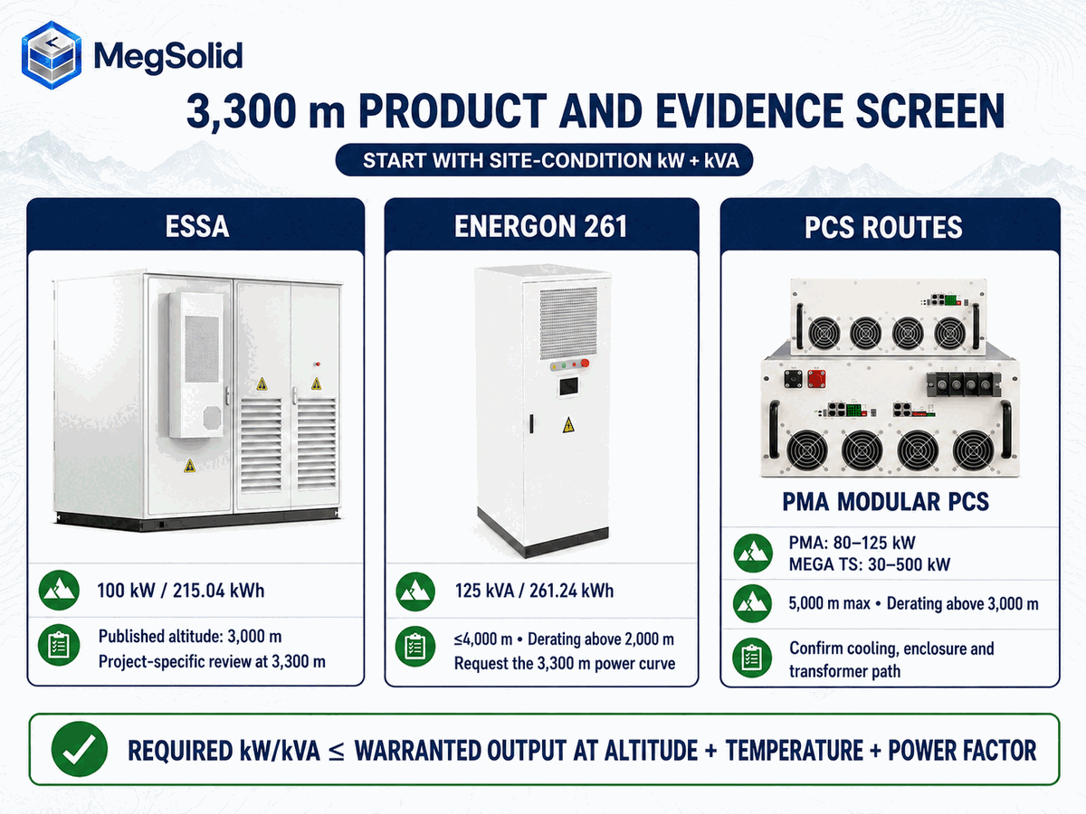
| ESSA outdoor cabinet series | Published altitude reference 3,000 m | Intelligent air cooling, IP54 | Use the 3,000 m reference for initial screening and confirm site-condition kW/kVA from the controlled project data |
| Energon 261.24 kWh platform | Maximum 4,000 m; derating above 2,000 m | Liquid cooling; controlled enclosure details required | Request the 125 kVA altitude curve and heat-rejection performance at site conditions |
| 5000INTL containerized BESS | Published altitude reference up to 4,000 m | Smart liquid cooling, IP55 | Confirm the container, PCS and auxiliary-system operating point as one project package |
The derating threshold and slope belong to a particular design. For example, the CPS ECB200KTL user manual, Figure 10-3 on page 175 shows rated output through 3,000 m and 70% at 4,000 m under that curve. Its separate temperature curve does not establish a combined altitude/temperature rule. Use this as an example of reading a controlled curve; obtain the curve for the MegSolid model actually offered.
The product pages for the MEGA transformer-integrated PCS, PMA modular PCS and R30KH3–R50KH3 hybrid inverter must be paired with the current controlled datasheet for the ordered model.
The PMA080, PMA0105 and PMA0125 modular PCS models publish different rated AC powers. Confirm the exact quoted identifier and its warranted kW/kVA at the site elevation, intake temperature, DC window and cooling condition.
High-Altitude BESS Derating Example at 3,300 m
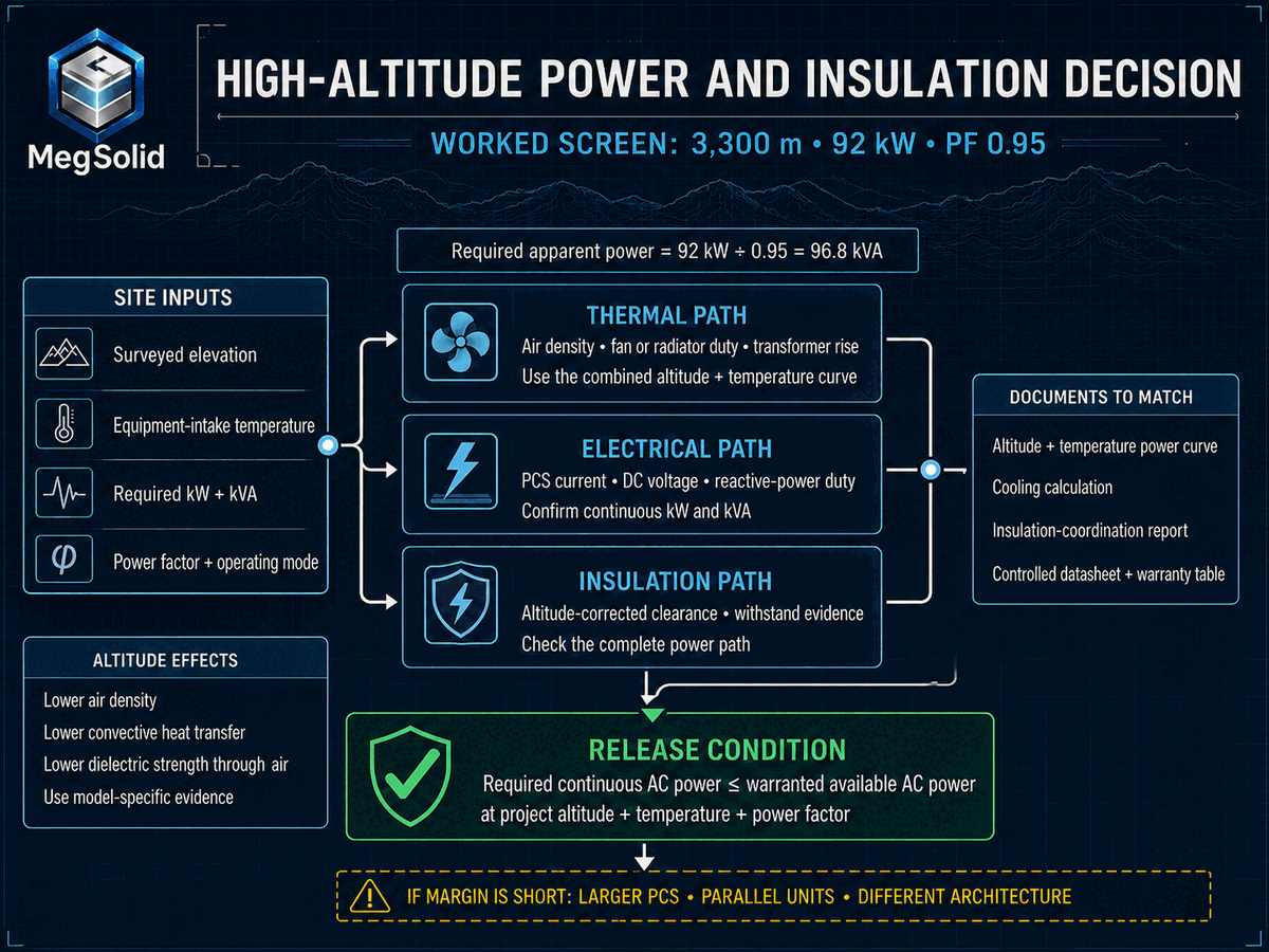
Consider a project at 3,300 m that needs 92 kW of continuous real power at 0.95 power factor. The figures demonstrate the selection method; the approved model curve and project warranty establish the final available output.
Required apparent power = required real power ÷ power factor
For the stated 92 kW load, S = 92 ÷ 0.95 = 96.84 kVA before design margin. Real power and apparent power must both pass the selected model’s site-condition limits. The following product screen identifies possible routes; it does not assign an unprovided derating factor to any of them.
| Candidate | Nameplate screen | Altitude screen at 3,300 m | What remains open |
|---|---|---|---|
| Two R50KH3 inverters | 100 kW total rated output | Above the 2,000 m derating threshold; below the 4,000 m maximum | Parallel architecture, per-unit curve, reactive-current capability, redundancy and thermal conditions |
| PMA0105 | 105 kW rated AC | Above the 3,000 m derating threshold; below the 5,000 m maximum | Available kW/kVA at 3,300 m, project enclosure, cooling and insulation coordination |
| MEGA0100TS | 100 kW rated, 110 kVA maximum apparent power | Above the 3,000 m derating threshold; below the 5,000 m maximum | Continuous kW and kVA at altitude/temperature, transformer heat rise and power-factor condition |
| ESSA0100B-0215 | 100 kW rated AC, 215.04 kWh nominal energy | Site is above the published 3,000 m altitude reference | Hold the standard configuration outside the published 3,000 m reference; require written approval of the exact extended-altitude build or select a higher-altitude architecture. |
| Energon | 125 kVA, 261.24 kWh | Above the 2,000 m derating threshold; below the 4,000 m maximum | Available kVA/kW at 3,300 m, temperature, cooling duty and ordered system configuration |
Illustrative second step: assume a supplier’s approved table retains 90% of a hypothetical 100 kVA continuous rating at the chosen elevation and temperature. Available apparent power is 90 kVA; at 0.95 power factor it supports at most 85.5 kW if no lower real-power limit applies. That fails the 92 kW duty by 6.5 kW. The corresponding nameplate screen is 92 ÷ (0.90 × 0.95) = 107.60 kVA, before margin and other limits. The 90% factor is an illustration, not a published MegSolid curve. A listed maximum apparent-power value such as MEGA0100TS’s 110 kVA must not be substituted for continuous site-rated output.
ESSA’s published altitude reference is 3,000 m. A standard configuration remains unapproved for this 3,300 m example until MegSolid supplies written engineering acceptance for the exact build, continuous kW/kVA, cooling and insulation at that elevation. Otherwise choose an architecture whose published operating range covers the site and obtain its reduced-power curve.
Screen the PCS before the single-line diagram is frozen
Send the surveyed elevation, hourly temperature range, continuous and transient kW/kVA, power factor, DC voltage range, one-line diagram and required enclosure rating. MegSolid can identify which model curves and insulation documents are still needed before a selection is released.
Temperature and Altitude Must Be Applied to the Same Operating Point
Two separate datasheet limits can look like a pass. A PCS rated 55 °C and 5,000 m still needs a power table at 55 °C and 5,000 m together.
The project should request a table or surface with at least:
- Elevation
- Equipment-intake temperature
- Continuous real power
- Continuous apparent power
- Power factor or reactive-power condition
- DC voltage
- Cooling-system status
- Enclosure and airflow configuration
- Allowed duration and recovery condition
If the supplier gives separate temperature and altitude factors, the calculation method must be stated. Multiplying, adding or choosing the lower factor can produce different answers. The warranty needs one approved result for each design operating point.
PMA PCS models publish operation from −30 to 60 °C, with derating above 45 °C, and altitude up to 5,000 m, with derating above 3,000 m. Energon publishes operation from −20 to 55 °C, with derating above 45 °C, and altitude up to 4,000 m, with derating above 2,000 m. A project at 3,500 m and 48 °C remains within the published maximum boundaries while sitting above both derating thresholds. The combined available-power table therefore determines the required PMA or Energon configuration.
The ESSA versus Energon derating test covers the hot-site selection method. A high-altitude project adds the air-density and insulation checks developed here.
Power Factor Can Consume the Remaining PCS Headroom
Factories and microgrids often need the PCS to supply or absorb reactive power while delivering real power. Semiconductor current and apparent-power limits still apply. An altitude-adjusted current or apparent-power limit can reduce the real-power capability available for the plant's kW target.
At 92 kW, the apparent-power requirement is 96.84 kVA at PF 0.95 and 102.22 kVA at PF 0.90. A continuous 100 kVA boundary cannot supply the second condition even before further derating. When the project requires simultaneous reactive support, verify the P–Q capability point as well as P ≤ P_available and S ≤ S_available; a selectable power-factor range does not guarantee full kW throughout that range.
Request capability evidence in the quadrant and operating mode the plant needs:
- Charging and discharging
- Grid-connected and off-grid operation
- Leading and lagging reactive power
- Unbalanced load where applicable
- Step load and motor starting
- Continuous and short-duration overload
The public R30KH3–R50KH3 data states an adjustable power factor from 0.8 leading to 0.8 lagging. The PMA family states −1 to +1. Those ranges describe control capability. Rated kW at every power factor, altitude and temperature still needs the curve.
Follow the Heat Path to Ambient Air
Cooling labels describe the internal heat-transfer architecture. Every practical BESS still rejects heat to the surroundings.
Forced-air equipment
R30KH3–R50KH3 and MEGA TS use forced air. At altitude, fan speed or volumetric airflow alone does not prove adequate heat removal. The supplier should state the intake condition, fan operating point, allowable pressure drop and component temperature rise at the project elevation.
Filters, louvers, acoustic treatments and ductwork add resistance. A high-altitude design with a dust filter or noise attenuator must include the final installed pressure drop, not a bare-PCS laboratory condition.
Liquid-cooled equipment
Liquid cooling carries heat from cells or power components to a heat exchanger. The final exchanger, dry cooler or chiller still transfers heat to ambient air. Thin air can reduce the capacity of that final heat-rejection stage. Pump flow and cold-plate temperature can remain normal while the radiator approaches its limit.
For Energon or 5000INTL, request coolant flow, supply/return temperature, pump margin, heat-exchanger duty, fan selection, auxiliary consumption and available system power at the site air density. The maintenance boundary for coolant, pumps and leaks is detailed in liquid-cooled BESS maintenance.
Isolation transformers and switchgear
The MEGA TS family includes an isolation transformer. A transformer releases heat through its windings, core, enclosure and surrounding air. Its temperature-rise evidence must cover elevation, load, harmonics, enclosure and ventilation. The built-in transformer gives the project a clear integrated boundary, but the project must still obtain the boundary's high-altitude rating.
Switchgear and protective devices also carry current and interrupt faults. Confirm their continuous-current, short-circuit and insulation capability at the installation altitude. A PCS curve does not qualify the adjacent breaker.
High-Altitude Insulation Coordination and Air Clearance
High-altitude insulation work is often squeezed into one line about “larger creepage and clearance.” That line can hide an error.
Clearance is the shortest path through air; creepage follows an insulating surface. Altitude correction applies to the clearance assessment under the applicable method; creepage also depends on working voltage, pollution degree and material group. Texas Instruments’ worked insulation example, page 10 uses a 1.29 clearance factor at 4,000 m: 3.00 mm × 1.29 = 3.87 mm. That illustrates the method for its stated PCB design; the BESS engineer must derive the actual base distance, insulation class and product-standard requirements for the supplied assembly.
The insulation review should identify:
- 1. Maximum continuous DC and AC working voltage
- 2. System earthing and overvoltage category
- 3. Pollution degree inside each compartment
- 4. Material group and comparative tracking information where required
- 5. Required impulse and power-frequency withstand levels
- 6. Basic, supplementary, reinforced or functional insulation boundary as applicable
- 7. Altitude correction method for air clearance
- 8. Clearances at busbars, terminals, contactors, fuses, breakers and surge devices
- 9. Field cable termination and connector geometry
- 10. Transformer and switchgear external-insulation evidence
IEC 60664-1 provides a framework for equipment within its voltage and frequency scope. Medium-voltage switchgear, transformers and other equipment use the product standards applicable to their voltage class and construction. The project insulation-coordination study must assign the correct standard to each component instead of applying one low-voltage table to the whole plant. An ABB medium-voltage breaker catalogue separately illustrates the same physical concern for external insulation and directs altitude correction through the applicable switchgear framework.
Ask for a Product-Level Evidence Pack
A technical offer should include more than an altitude line in the environmental table. Require:
- Model-specific maximum operating altitude and derating threshold
- Available continuous kW and kVA versus altitude
- Combined altitude and intake-temperature method
- Conditions for power factor, DC voltage, grid voltage and cooling mode
- Component temperature limits and thermal-test or calculation basis
- Fan, radiator or heat-exchanger selection at project air density
- Insulation-coordination report and altitude-corrected clearances
- Withstand-test evidence with the supplied configuration and voltage class
- Altitude ratings for PCS, battery cabinet, transformer, switchgear, DC protection and auxiliaries
- Control response, alarm thresholds, recovery and event logging during derating
- Warranty statement for the exact surveyed elevation and operating points
- Deviations, special options and serial-controlled configuration changes
The evidence needs document numbers and revisions. A curve pasted into an email can be separated from the model, firmware or enclosure configuration that produced it.
Treat the integrated cabinet as one controlled assembly, with a named cell, PCS, cooling package, transformer where fitted, protection devices and software revision. The ESSA outdoor cabinet page and 215 kWh cabinet engineering page provide the starting data. Neither replaces the written available-power and insulation evidence for a site beyond the published altitude boundary.
FAT Checks the Supplied Build; SAT Checks the Installed Boundary
A normal sea-level FAT facility cannot reproduce a 3,500 m atmosphere unless it has suitable altitude simulation equipment. FAT can still prove the control and electrical functions tied to the approved high-altitude design.
FAT should confirm:
- Correct model, power stage, transformer, fan or cooling hardware and firmware
- Derating setpoints and altitude configuration where the product uses them
- Temperature-sensor and fan/pump feedback plausibility
- Alarm, output-limiting, latch and recovery sequence
- kW, kVA, power-factor, current and temperature tag export
- Insulation and withstand tests required by the approved design and applicable standards
- Document traceability from test specimen to shipped serial number
- Failure response for a fan, pump, sensor or communications fault
Label the evidence by what it actually establishes: a calculation predicts performance within its assumptions; a component qualification covers that component; a type test covers its specimen and conditions; a sea-level FAT checks the shipped build and functions; SAT records the installed site. Ask the design authority to close any gap between those scopes. A sea-level full-power run alone does not establish sustained full power at altitude.
SAT should confirm:
- Surveyed pad elevation and installed equipment model
- Cooling clearances, ducting, filters and recirculation risk
- Ambient and equipment-intake temperature sensors
- Fan, pump, radiator and auxiliary operation
- AC and DC voltage, current, kW, kVA and power factor
- Derating warning and output-limit behaviour through an approved test method
- Transformer and switchgear installation against the altitude-rated design
- Time synchronization and event export to the site EMS/SCADA
- Stable operation at the highest safely available commissioning duty
- Open items for seasonal or full-load verification
The BMS and EMS communication architecture is relevant because the event sequence must show whether temperature, current or another limit caused the power reduction.
Do Not Hide Altitude Margin Inside Extra Battery kWh
Extra battery energy does not raise the PCS power available at the site condition. A 500 kWh battery behind an altitude-adjusted 80 kW PCS boundary still delivers no more than 80 kW at that operating point.
Power and energy therefore need separate acceptance lines:
Power screen: required site kW/kVA ≤ warranted PCS output at project conditions
Energy screen: required delivered AC kWh ≤ warranted usable AC energy over the defined SOC window and duty
The battery-energy calculation should include conversion losses, temperature, SOC limits, degradation allowance and auxiliary consumption. The altitude review adds PCS and cooling constraints. Run the energy study separately.
This distinction also prevents an oversized cabinet from being presented as the remedy for a missing altitude curve. The site operating point determines whether the project needs a larger PCS class, parallel units, a revised power target, a different cooling architecture or a model with a higher altitude boundary.
Put High-Altitude Requirements Into the Purchase Order
The purchase order should fix the operating points and the evidence required for acceptance. Include:
- 1. Surveyed installation elevation and tolerance
- 2. Minimum and maximum equipment-intake temperature
- 3. Continuous and transient kW/kVA in charge and discharge
- 4. Required power-factor and reactive-power range
- 5. DC voltage window and battery configuration
- 6. AC voltage, frequency, earthing and grid mode
- 7. Maximum allowed derating at each design operating point
- 8. Cooling and enclosure configuration as installed
- 9. Altitude ratings for every series component in the power path
- 10. Insulation-coordination study and applicable standards
- 11. Model-specific altitude/temperature curves and calculation method
- 12. Derating alarms, SCADA tags and recovery logic
- 13. FAT and SAT procedures with pass/fail values
- 14. Warranty coverage at the stated elevation and duty
- 15. Required site spares and service response
- 16. Controlled datasheet, BOM, single-line diagram and document revisions
This list gives procurement a commercial lever. If warranted high-altitude output is missing, the offer stays open. Compare suppliers on delivered capability and evidence, not on the maximum-altitude label.
Select the Architecture From the Site Operating Point
R30KH3–R50KH3 provides a three-phase hybrid-inverter route with grid/off-grid operation, IP65 enclosure, operation up to 4,000 m and derating above 2,000 m. The current product page identifies R50KH3 as the four-MPPT option; that feature should not be assigned to every model without the ordered datasheet. PMA provides modular 80–125 kW PCS choices with a 5,000 m maximum and derating above 3,000 m for integration into an engineered cabinet and cooling boundary. MEGA TS covers 30–500 kW with a built-in isolation transformer, forced air and the same 5,000 m maximum / above-3,000 m derating boundary.
For integrated C&I storage, ESSA offers 30–100 kW cabinet models, up to 215.04 kWh in ESSA0100B-0215, intelligent air cooling, IP54 and integrated EMS functions. Its published altitude value is 3,000 m. Energon offers a 125 kVA / 261.24 kWh liquid-cooled route with a 4,000 m maximum and derating above 2,000 m. The public product pages identify 280 Ah LFP cells for ESSA0100B-0215 and 314 Ah LFP cells for Energon 261. Any project sold as a hybrid solid-state configuration requires that cell type to be stated consistently in the controlled quotation, datasheet and BOM.
The product advantage is matching the architecture to evidence. A built-in transformer cuts field interfaces. An integrated cabinet narrows the responsibility gap. Liquid cooling can hold cell temperature more tightly. The high-altitude output and insulation package then documents how the selected advantage performs at the actual site.
The broader project boundary is covered in MegSolid C&I energy-storage engineering.
Close the Selection With One Warranted Operating Table
The final approval document should be short enough for procurement and exact enough for engineering. Use one row per required operating point.
| Acceptance field | Entry to agree before purchase and verify at handover |
|---|---|
| Installation condition | Surveyed pad elevation and tolerance; minimum/normal/maximum equipment-intake temperature; as-installed enclosure and cooling. |
| Operating point | Charge/discharge, grid-connected/off-grid, AC/DC voltage window, required continuous kW, kVA and simultaneous reactive-power duty. |
| Warranted available output | Supplier-entered kW and kVA at the same elevation, temperature and mode, with curve/report number and revision. No value means this operating point remains open. |
| 92 kW worked-example check | At PF 0.95 the requirement is 96.84 kVA. Enter the offered site-rated P and S separately; accept only if both cover the duty plus the project’s agreed margin. |
| Thermal condition | Record intake temperature, fan/pump/heat-exchanger state, output, component temperatures and stabilization criterion for the agreed test duty. |
| Power-path components | PCS, battery cabinet, transformer, switchgear, breakers, DC protection and auxiliaries must each cover the site voltage, current and altitude. |
| Insulation evidence | Applicable product standard, working/impulse voltage, insulation class, altitude correction, drawings and relevant withstand report; identify field cable terminations. |
| Control event | Agreed warning/limit/recovery thresholds, delays and allowed output; verify through an approved non-destructive functional test. |
| Recorded test boundary | Meter location and accuracy, kW/kVA/PF, AC/DC values, ambient/intake sensors, time-synchronized trend files and operating duration. |
| Deferred verification | Document any unavailable seasonal, full-load or altitude-simulation condition; state the remaining evidence, responsible party and completion condition. |
| Warranty and configuration | Signed altitude/duty coverage, approved BOM and firmware, deviations, service responsibilities and change control. |
| Acceptance record | Owner/EPC/supplier sign-off against the agreed values; retain the source trend files and unresolved-item list. |
Keep the calculated requirement, the supplier’s warranted limit and the measured result in separate fields. Sign off only the conditions actually demonstrated; carry an unavailable seasonal or full-load condition into the agreed completion plan.
Confirm the high-altitude power and insulation package before purchase
Send the surveyed elevation, intake-temperature extremes, continuous and transient kW/kVA, power factor, DC voltage window, one-line diagram and operating modes. Ask MegSolid to identify the matching architecture, its available-power curve and insulation evidence, and any open project conditions. This lets the quotation address the site duty without assuming an unpublished high-altitude capability.
FAQ
1. Why does a BESS PCS derate at high altitude?
Lower air density can reduce heat removal and air-insulation margins. Thermal derating limits current or output to control temperature. Insulation, working voltage and switching/protection suitability require their own altitude assessment; lowering kW alone does not establish those ratings.
2. Does a 5,000 m maximum altitude mean full power at 5,000 m?
No. The maximum permits operation only within the controlled conditions. PMA and MEGA TS publish derating above 3,000 m, so their available output above that threshold requires the model-specific curve.
3. At what altitude does the R50KH3 start derating?
The R30KH3, R40KH3 and R50KH3 public data states derating above 2,000 m and a maximum altitude of 4,000 m.
4. How should ESSA0100B-0215 be screened for a 3,300 m site?
Its published altitude reference is 3,000 m, below this 3,300 m site. Do not approve the standard configuration from that reference alone. Obtain written acceptance and supporting power, cooling and insulation evidence for the exact extended-altitude build, or select a model whose published range covers the site and verify its reduced output.
5. Does extra battery capacity compensate for altitude derating?
No. Additional kWh can extend duration, but it cannot raise the continuous power allowed by the PCS, transformer, switchgear or cooling system at the site condition.
6. How should temperature and altitude derating be combined?
Use the manufacturer's controlled method or a warranted table for the exact operating point. Do not add or multiply independent factors unless the approved document tells the project to do so.
7. Why does power factor matter in a high-altitude PCS selection?
A lower power factor requires more apparent power and current for the same real kW. The altitude-adjusted current or kVA boundary therefore leaves less room for reactive-power duty.
8. Is liquid cooling unaffected by altitude?
No. The liquid loop moves heat internally, while the radiator, dry cooler or chiller eventually rejects that heat to ambient air. The final heat exchanger and its fans must be selected for site air density.
9. Does altitude require more creepage distance?
Altitude correction directly addresses clearance through air under the applicable insulation-coordination method. Creepage selection follows working voltage, pollution degree and material group. The complete design must apply the correct rule to each path.
10. What insulation evidence should an EPC request?
Request the insulation-coordination calculation, altitude-corrected air clearances, pollution degree, material group where relevant, withstand levels, applicable standards and test reports tied to the supplied model.
11. Can a sea-level FAT prove high-altitude full power?
No. A normal sea-level full-power test does not reproduce the site’s reduced air pressure and density. FAT can verify the supplied build, settings and functions; the high-altitude capability still needs an accepted design/qualification basis and site evidence within the agreed verification conditions.
12. Which MegSolid PCS has a built-in isolation transformer?
The MEGA0030TS–MEGA0500TS family includes isolation transformers. Its altitude maximum is 5,000 m, with derating above 3,000 m.
13. Is PMA PCS an outdoor complete BESS cabinet?
No. PMA is a modular PCS. Its power compartment is IP20 and control compartment IP6X, so the project must provide the approved enclosure, cooling, battery and system integration.