
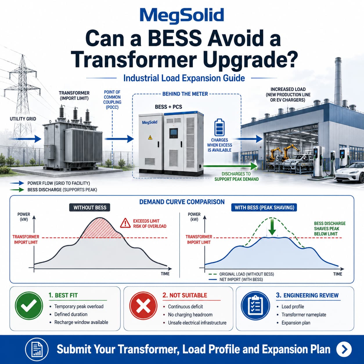
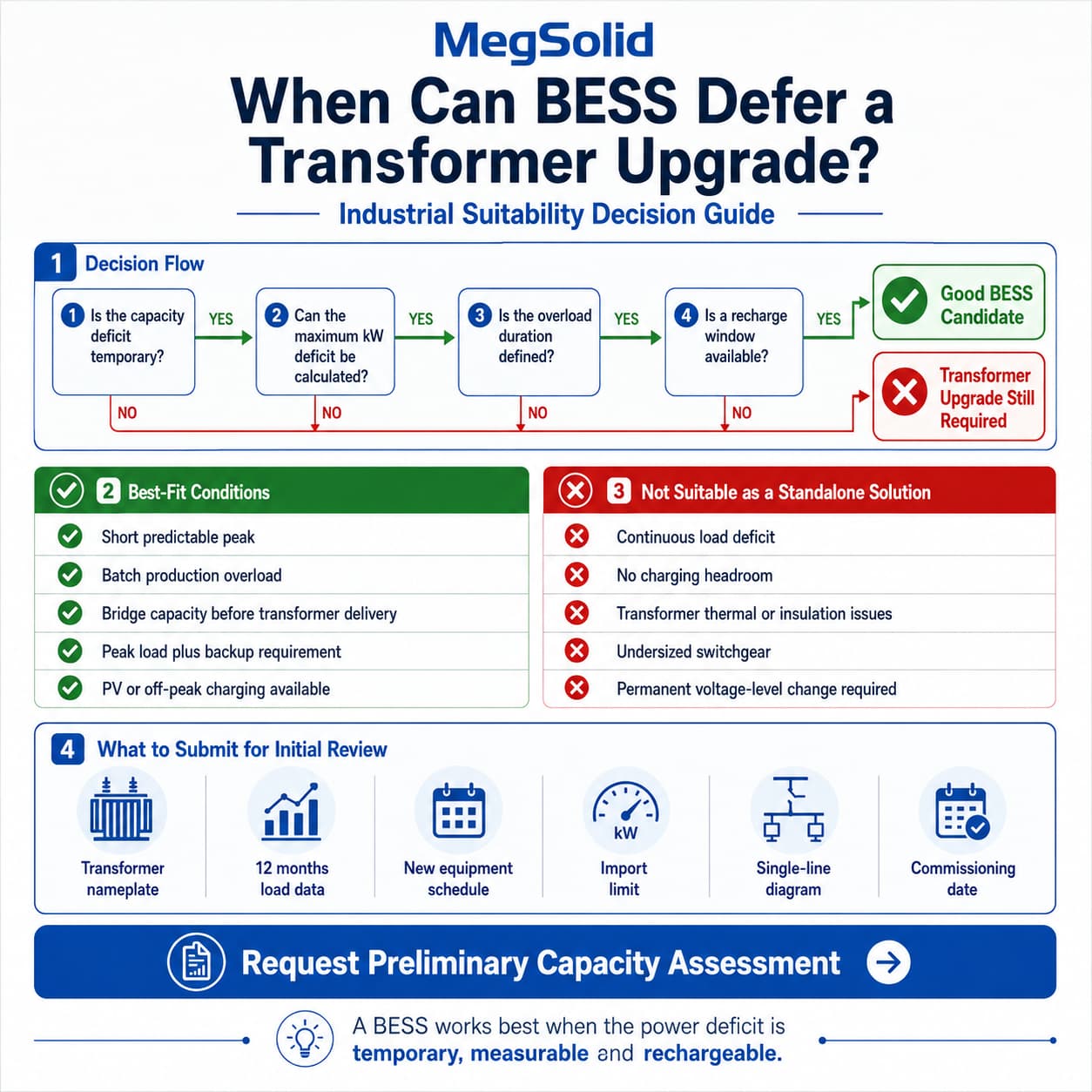
A BESS can defer a transformer upgrade only when the capacity deficit is temporary, measurable and followed by a practical recharge window.
The project should meet three basic conditions:
- The maximum power deficit can be calculated in kW or kVA
- The overload period has a defined duration
- The battery can recharge before the next peak
MegSolid evaluates transformer-capacity projects by separating PCS power from battery energy.
The PCS must cover the maximum power deficit. The battery must sustain that output for the required duration.
A BESS cannot support a permanent capacity deficit indefinitely. If the new production load operates continuously and no charging headroom exists, the factory will still require a transformer or grid-connection upgrade .
Request a Preliminary Transformer Capacity Assessment
For an initial engineering review, submit:
| Required Information | What to Provide |
|---|---|
| Transformer | Nameplate photo, rated kVA and voltage |
| Existing demand | Twelve months of interval load data |
| New equipment | Rated power and operating schedule |
| Import limit | Utility, breaker or internal operating limit |
| Electrical system | Current single-line diagram |
| Project timing | Target production and commissioning date |
MegSolid’s preliminary review can return:
- Estimated transformer-capacity deficit
- Preliminary PCS power range
- Preliminary battery-duration requirement
- Recommended charging window
- Initial EMS import-limit strategy
- Cabinet or containerized system direction
- Missing data required before quotation
Recommended Button: Request Preliminary Capacity Assessment
Is the Project Suitable for BESS?
The first decision is not which battery cabinet to purchase.
The first decision is whether the factory has a temporary peak problem or a permanent infrastructure problem.
| Project Condition | BESS Suitability | Procurement Direction |
|---|---|---|
| Short, predictable peak with off-peak recharge | High | Proceed with PCS and energy sizing |
| Batch-production or seasonal overload | High | Model annual cycles and peak duration |
| Temporary bridge before transformer delivery | Medium to high | Compare bridge period with BESS lifecycle use |
| Continuous deficit for most of the day | Low | Upgrade transformer or grid connection |
| No spare grid or PV capacity for charging | Low | BESS cannot sustain the daily cycle |
| Transformer has thermal or insulation problems | Low | Repair or replace infrastructure first |
| Existing switchgear is undersized | Low | Electrical upgrade remains necessary |
| Peak load plus backup-power requirement | High | Evaluate combined capacity and resilience use |
BESS is strongest when the capacity problem occurs during defined production windows.
Examples include:
- A new process line creates a two-hour afternoon peak
- Several compressors overlap during shift changes
- EV charging coincides with maximum factory demand
- Refrigeration demand rises during hot afternoons
- A batch heater runs for limited production cycles
- Grid reinforcement will not be completed before production starts
When the capacity deficit is continuous, storage only moves the problem.
The battery eventually reaches its minimum SOC and must recharge from the same constrained electrical system.
BESS vs. Transformer Upgrade vs. Hybrid Strategy
A factory should compare three alternatives before issuing a purchase order.
| Decision Factor | BESS Capacity Support | Transformer Upgrade | Hybrid Strategy |
|---|---|---|---|
| Best load profile | Temporary peaks | Continuous load growth | Immediate peak plus future growth |
| Deployment | Potentially faster | Usually slower | Phased |
| Long-term capacity | Limited by PCS and energy | Permanent | Expandable |
| Recharge requirement | Required | Not applicable | Required during bridge period |
| Backup capability | Available | Not included | Available |
| Peak shaving | Available | Not included | Available |
| Civil and MV work | Potentially lower | Usually substantial | Deferred or staged |
| Future use | Peak shaving, backup, PV buffering | Permanent capacity | BESS remains after upgrade |
| Main risk | Incorrect load-duration calculation | Long approval and construction cycle | Coordination of both investments |
The hybrid strategy can be commercially attractive when production cannot wait for a new transformer.
The BESS provides capacity support during the delivery and construction period. After the transformer upgrade, the same system can continue operating for:
- Peak shaving
- Backup power
- Solar self-consumption
- Diesel optimization
- Demand-limit control
- Microgrid operation
DOE continues to identify limited manufacturing capacity, extended procurement timelines and supply-chain dependence as active constraints in the U.S. distribution-transformer market. These conditions are market-specific, but they demonstrate why industrial sites may need a capacity bridge while permanent reinforcement is being delivered.
Calculate the Real Transformer Capacity
Transformer nameplate kVA does not equal usable factory kW.
The approximate active-power relationship is:
Active Power = Apparent Power × Power Factor
For a 1,000kVA transformer:
| Power Factor | Approximate Active Power |
|---|---|
| 0.85 | 850kW |
| 0.90 | 900kW |
| 0.95 | 950kW |
| 0.98 | 980kW |
This is only the first calculation.
The engineering team must also review:
- Transformer type and cooling method
- Ambient and enclosure temperature
- Daily loading pattern
- Harmonic currents
- Voltage unbalance
- Neutral loading
- Transformer condition and age
- Main breaker rating
- Busbar and cable capacity
- Protection settings
There is no universal requirement that every transformer must remain below 80% of nameplate rating.
Schneider Electric states that its low-voltage dry-type transformers are designed for continuous full load under defined ideal conditions. Its liquid-filled transformer guidance also allows rated operation under specified ambient conditions, including a 30°C daily average and 40°C maximum.
Higher ambient temperature may require derating. Schneider’s guidance for applicable low-voltage transformers specifies a VA reduction when the 24-hour average ambient exceeds 30°C.
Nonlinear loads also require attention.
VFDs, rectifiers, chargers and power-electronic equipment create harmonic currents that can increase transformer heating and voltage distortion. Eaton recommends evaluating the proportion of harmonic load rather than assuming all transformer kVA produces the same thermal effect.
Calculate the Capacity Deficit
The preliminary BESS power requirement is:
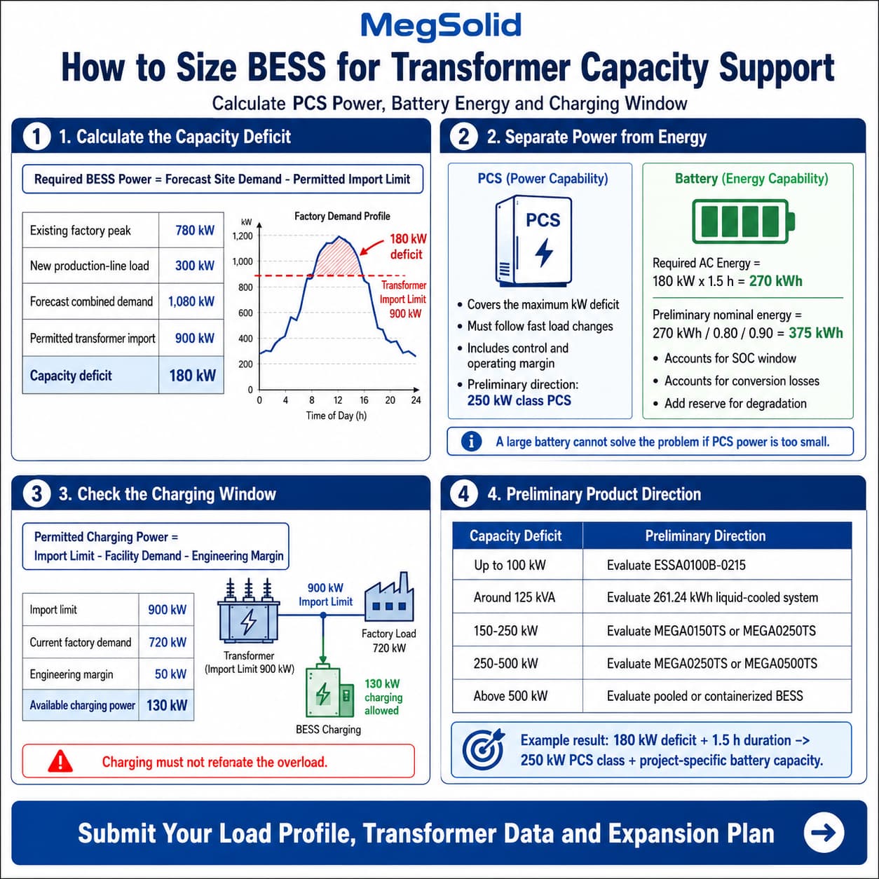
Required BESS Discharge Power = Forecast Site Demand − Permitted Import Limit
Assume a factory has the following operating profile:
| Engineering Input | Illustrative Value |
|---|---|
| Existing factory peak | 780kW |
| New production-line load | 300kW |
| Forecast combined demand | 1,080kW |
| Permitted transformer import | 900kW |
| Calculated capacity deficit | 180kW |
The BESS must supply approximately 180kW while the combined facility load exceeds the 900kW threshold.
The final PCS rating should also account for:
- Forecast error
- Load-step response
- PCS operating margin
- Auxiliary consumption
- Reactive-power requirements
- Control deadband
- Future production variation
A 250kW-class PCS is therefore a more practical preliminary direction than selecting a PCS at exactly 180kW.
This is not final sizing. The actual requirement depends on interval data, power factor and the maximum simultaneous load.
Complete the Power and Energy Calculation
PCS power determines how much transformer demand can be removed.
Battery energy determines how long the BESS can maintain that reduction.
Assume the 180kW deficit lasts for 90 minutes:
Required AC Energy = 180kW × 1.5 hours = 270kWh
Nominal battery capacity must be higher than the calculated AC energy.
For an illustrative preliminary calculation:
| Calculation Step | Illustrative Result |
|---|---|
| Capacity deficit | 180kW |
| Peak duration | 1.5 hours |
| Required AC energy | 270kWh |
| Assumed usable SOC window | 80% |
| Assumed conversion factor | 90% |
| Preliminary nominal energy | 375kWh |
| Preliminary PCS direction | 250kW class |
| Final configuration | Requires duty-cycle review |
The preliminary nominal-energy calculation is:
270kWh ÷ 0.80 ÷ 0.90 = 375kWh
Additional capacity may be required for:
- End-of-life performance
- Battery degradation
- Temperature effects
- Auxiliary loads
- Forecast uncertainty
- Emergency reserve
This example points toward a 250kW MEGA PCS with project-specific battery capacity.
It does not point toward one 100kW/215.04kWh ESSA0100B-0215 cabinet.
For broader peak-shaving economics, review the C&I peak shaving ROI engineering guide.
Charging Can Create a Second Capacity Problem
A BESS must recover its SOC after supporting the factory peak.
Charging increases transformer demand unless the energy comes from verified surplus PV.
The dynamic charging limit should be:
Permitted BESS Charging Power = Import Limit − Facility Demand − Engineering Margin
Assume:
| Charging Condition | Illustrative Value |
|---|---|
| Import limit | 900kW |
| Current factory demand | 720kW |
| Engineering margin | 50kW |
| Available charging power | 130kW |
Although the PCS may be rated at 250kW, grid charging should be limited to 130kW under this operating condition.
Charging power may increase when:
- Factory demand decreases
- Surplus PV becomes available
- A production line stops
- The permitted import limit changes
- SOC must recover before a forecast peak
If no charging headroom exists, the BESS cannot repeat the required operating cycle.
This must be confirmed before the supplier finalizes battery capacity.
EMS Import-Limit Control
Transformer support requires real-time control.
A fixed charge-and-discharge schedule is not sufficient when production demand changes throughout the day.
The EMS should monitor:
- Point-of-connection power
- Transformer loading
- Facility demand
- Battery SOC
- PCS availability
- PV production
- New-line operating status
- Meter and communication health
The basic control logic is:
- The point-of-connection meter reports facility import.
- The EMS compares import with the configured limit.
- The PCS discharges as the threshold is approached.
- PCS output follows changes in factory demand.
- The EMS preserves the minimum SOC reserve.
- Charging is limited until import headroom becomes available.
- A safe fallback mode activates after communication loss.
NREL research found that BESS control setpoints directly affect transformer loading and storage utilization. Poorly selected thresholds can leave the battery underused or reduce its ability to control peaks.
Review the BMS and EMS communication architecture guide for signal and operating-limit coordination.
Preliminary MegSolid Product Direction
Product selection must follow the calculated power deficit and duration.
| Calculated Requirement | Preliminary Direction |
|---|---|
| Up to 100kW | Evaluate ESSA0100B-0215 |
| Around 125kVA | Evaluate 261.24kWh liquid-cooled system |
| 150kW requirement | Evaluate MEGA0150TS with project-specific battery capacity |
| 180–250kW requirement | Evaluate MEGA0250TS with project-specific battery capacity |
| 250–500kW requirement | Evaluate MEGA0250TS or MEGA0500TS |
| Above 500kW | Evaluate pooled cabinets or containerized BESS |
| Continuous deficit | Compare directly with transformer reinforcement |
MEGA PCS for Higher-Power Capacity Support
The MEGA PCS series provides the following published ratings:
| Model | Rated Power | Maximum Apparent Power |
|---|---|---|
| MEGA0100TS | 100kW | 110kVA |
| MEGA0150TS | 150kW | 165kVA |
| MEGA0250TS | 250kW | 275kVA |
| MEGA0500TS | 500kW | 550kVA |
The reviewed technical source lists:
- Adjustable power factor from 1 lagging to 1 leading
- Grid-current THD below 3%
- Automatic on-grid and off-grid operation
- 110% long-term overload
- RS485 and CAN BMS communication
- RS485 and TCP/IP EMS communication
These are PCS ratings. They do not prove that every connected battery configuration can provide the same output under all SOC, voltage and temperature conditions.
Review the MegSolid MEGA PCS specifications and the C&I energy storage inverter buying guide.
ESSA0100B-0215 for Deficits Up to 100kW
The ESSA0100B-0215 is an intelligent air-cooled C&I cabinet.
| Parameter | Verified Value |
|---|---|
| Rated AC power | 100kW |
| Nominal energy | 215.04kWh |
| Battery configuration | 1P240S |
| Nominal voltage | 768V |
| Battery voltage range | 672–850V |
| Cooling | Intelligent air cooling |
| Operating temperature | 0–45°C |
| Enclosure | IP54 |
| Net weight | 3,900kg |
This model may be evaluated when the calculated deficit remains within 100kW and the required duration matches the available system energy.
It must not be described as liquid-cooled or hybrid solid-state.
Review the 100kW 215kWh air-cooled C&I energy storage system and the 215kWh cabinet engineering guide.
261.24kWh Liquid-Cooled System
The 261.24kWh system has a published rated AC power of 125kVA.
| Parameter | Verified Value |
|---|---|
| Rated energy | 261.24kWh |
| Rated AC power | 125kVA |
| Cell chemistry | LFP, 314Ah |
| Nominal DC voltage | 832V |
| DC voltage range | 676–936V |
| Cooling | Liquid cooling |
| Adjustable power factor | -1 to +1 |
| Operating temperature | -20–55°C, derated above 45°C |
The published 90% value is maximum system efficiency. It must not be presented as guaranteed round-trip efficiency.
The reviewed product source identifies LFP cells and does not verify this model as hybrid solid-state.
Cabinet, Container or Hybrid Deployment?
The physical architecture should follow power, duration and connection requirements.
| Project Condition | Recommended Format |
|---|---|
| Deficit below 100–125kW | One C&I cabinet may be evaluated |
| Separate low-voltage load centres | Distributed cabinets |
| 150–500kW centralized deficit | Engineered battery plus MEGA PCS |
| Long-duration support | Pooled cabinets or container |
| Medium-voltage connection | Containerized or centralized architecture |
| Future phased expansion | Modular cabinet or pooled system |
| Redundant power requirement | Multiple PCS or containerized configuration |
Use BESS as a Capacity Bridge
A capacity-bridge project has a defined beginning and end.
The factory may need additional power now, while the larger transformer or grid reinforcement will not be commissioned for another 12–36 months.
The engineering review should define:
- Required bridge period
- Maximum daily capacity deficit
- Expected transformer-delivery date
- Production schedule during the bridge
- Battery cycle frequency
- Recharge availability
- BESS use after reinforcement
After permanent capacity becomes available, the BESS should retain a viable operating role.
Possible post-upgrade uses include:
- Demand-charge reduction
- Backup power
- PV energy shifting
- Zero-export control
- Grid-support functions
- Diesel reduction
This avoids purchasing a temporary asset with no long-term operating value.
What MegSolid Verifies Before Recommending a System
MegSolid should verify the following before issuing a product recommendation:
- Completeness of interval-load data
- Transformer operating margin
- New-load operating schedule
- Required PCS kW and kVA
- Battery duration and SOC window
- Charging and recharge strategy
- Meter and EMS architecture
- Model-specific operating limitations
- FAT simulation conditions
- Required site measurements
Review the MegSolid C&I energy storage solution for wider system architectures.
RFQ Data: Initial Review vs. Detailed Engineering
A long technical form can reduce inquiry completion.
The first submission should request only the information required to determine whether the project is viable.
Required for Initial Review
- Transformer nameplate photo
- Twelve months of interval load data
- New-equipment power and schedule
- Current single-line diagram
- Existing import limit
- Target commissioning date
Recommended for Detailed Engineering
- Transformer impedance
- Transformer condition report
- Power-factor history
- Harmonic measurements
- Switchgear and cable ratings
- PV interval-production data
- Protection settings
- Site ambient conditions
- Required backup loads
- Utility connection requirements
Use the C&I BESS procurement checklist and the commercial energy storage procurement guide to structure the full technical RFQ.
Application-Specific FAT and SAT
Testing should focus on transformer-limit control rather than repeating every generic BESS test.
The FAT should verify:
- Meter-signal simulation
- Dynamic import limiting
- PCS load-following response
- Maximum charging limit
- Minimum SOC reserve
- Meter-loss fallback
- EMS communication-loss response
- Alarm and event logging
The SAT should confirm:
- Real transformer loading
- Import-limit response
- PCS active and reactive output
- Battery SOC recovery
- Charging-limit operation
- Response during actual production load changes
Review the BESS Factory Acceptance Testing guide before agreeing on acceptance criteria.
Final Procurement Recommendation
A BESS can defer a transformer upgrade when the capacity deficit is temporary, predictable and rechargeable.
The correct process is:
- Analyse interval-load data.
- Confirm the transformer’s real operating limit.
- Add the forecast production load.
- Calculate the maximum power deficit.
- Measure the duration of each deficit.
- Confirm the available recharge window.
- Size PCS power and battery energy separately.
- Compare BESS with transformer and hybrid alternatives.
- Verify EMS limit control through FAT and SAT.
- Define the BESS role after any future transformer upgrade.
BESS should not conceal an unsafe or permanently undersized electrical system.
It should release temporary industrial capacity where controlled charging and discharging can keep the site within verified electrical limits.
FAQ
Q1: Can BESS completely replace a larger transformer?
Only under specific load-profile conditions.When the deficit is temporary and the battery can recharge before the next peak, BESS may defer or avoid an immediate upgrade. A continuous deficit normally requires permanent reinforcement.
Q2: Can BESS support production while a new transformer is on order?
Yes, when the bridge-period demand, PCS power, battery duration and recharge window are clearly defined.The BESS should also have a planned use after the new transformer is commissioned.
Q3: What happens to the BESS after the transformer upgrade?
It can continue operating for peak shaving, backup power, PV energy shifting, demand-limit control or microgrid support.These post-upgrade functions should be included in the initial commercial evaluation.
Q4: Can a 100kW BESS create 100kW of additional factory capacity?
It can offset demand up to its verified discharge capability while adequate SOC is available.The duration depends on usable battery energy and the operating reserve.
Q5: Is an 80% transformer-loading limit always required?
No.Permitted loading depends on transformer design, temperature, duty cycle, harmonics, condition and applicable standards.
Q6: How should end-of-life capacity be included?
The battery should be sized to meet the agreed capacity-support requirement at the defined end-of-life point.This normally requires degradation reserve above the initial AC energy calculation.
Q7: Can the EMS control transformer loading and zero export?
Yes, when the metering and control architecture supports both functions.The project must define which limit takes priority and what happens after meter or communication failure.
Q8: Can multiple BESS cabinets support separate load centres?
Yes.Distributed cabinets may support separate low-voltage areas, but their meters, SOC limits and EMS commands must be coordinated.
Q9: Is transformer condition testing required?
It is strongly recommended when the transformer is old, heavily loaded, overheating or showing abnormal oil, insulation or protection results.BESS should not be used to hide an existing equipment defect.
Q10: When is a transformer upgrade still necessary?
An upgrade is usually required when the load increase is continuous, the transformer is already thermally stressed, switchgear is inadequate, voltage must change or no practical charging window exists.
Q11: Can battery storage increase factory electrical capacity?
Battery storage can release temporary usable capacity by discharging when demand approaches the transformer or grid-import limit.It does not create unlimited permanent capacity.
Q12: How do you size BESS to avoid transformer overload?
Subtract the permitted transformer import from forecast facility demand to calculate PCS power.Then calculate battery energy from the duration of that deficit, SOC window, losses and degradation reserve.
Q13: What data should a factory submit?
Submit interval load data, transformer specifications, new-equipment demand, operating schedules, import limits, PV production and the current single-line diagram.